4.5 Connecting to the Lines to be Measured (Preparing for Current Measurement)
46
Be sure to read the "Usage Notes" (p.6) before attaching to the lines.
Connect the voltage cords and clamp sensors to the measurement line as shown in the connec-
tion diagram on the screen. (To ensure accurate measurement, consult the connection diagram*
while making the connections.)
*: The diagram appears when the wiring mode is selected. (p.39)
4.5 Connecting to the Lines to be Measured
(Preparing for Current Measurement)
To avoid electric shock and short-circuit accidents, do not attach any unneces-
sary cables.
To avoid risk of electric shock, turn off the supply of electricity to the measure-
ment circuit before making connections.
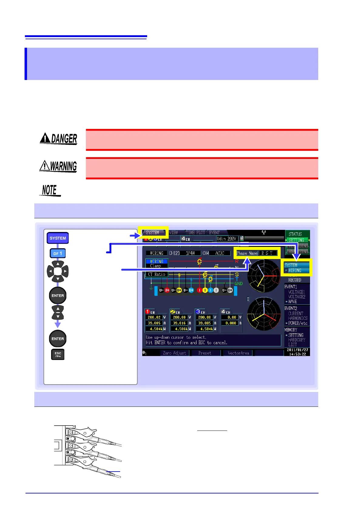
The phases are named R, S, and T on the wiring diagram display. Substitute with
equivalent names such as L1,L2, and L3 or U,V, and W, as appropriate.
Changing the phase names
Display the
pull-down menu
Select the
connection mode
Accept setting
Cancel
[SYSTEM] screen
[Phase Name]
[WIRING]
Accepting the settings will cause the
selected phase names to be shown
on the connection diagram. (p.40)
Attach voltage cords to measurement lines
Securely clip the leads to metal parts such as terminal screw ter-
minals or bus bars.
Example: Secondary side of breaker
L1000 Voltage Cord
 Loading...