4.4 Setting the Vector Area (Tolerance Level)
45
Chapter 4 Configuring the Instrument before Measurement (SYSTEM - SYSTEM screen)
4
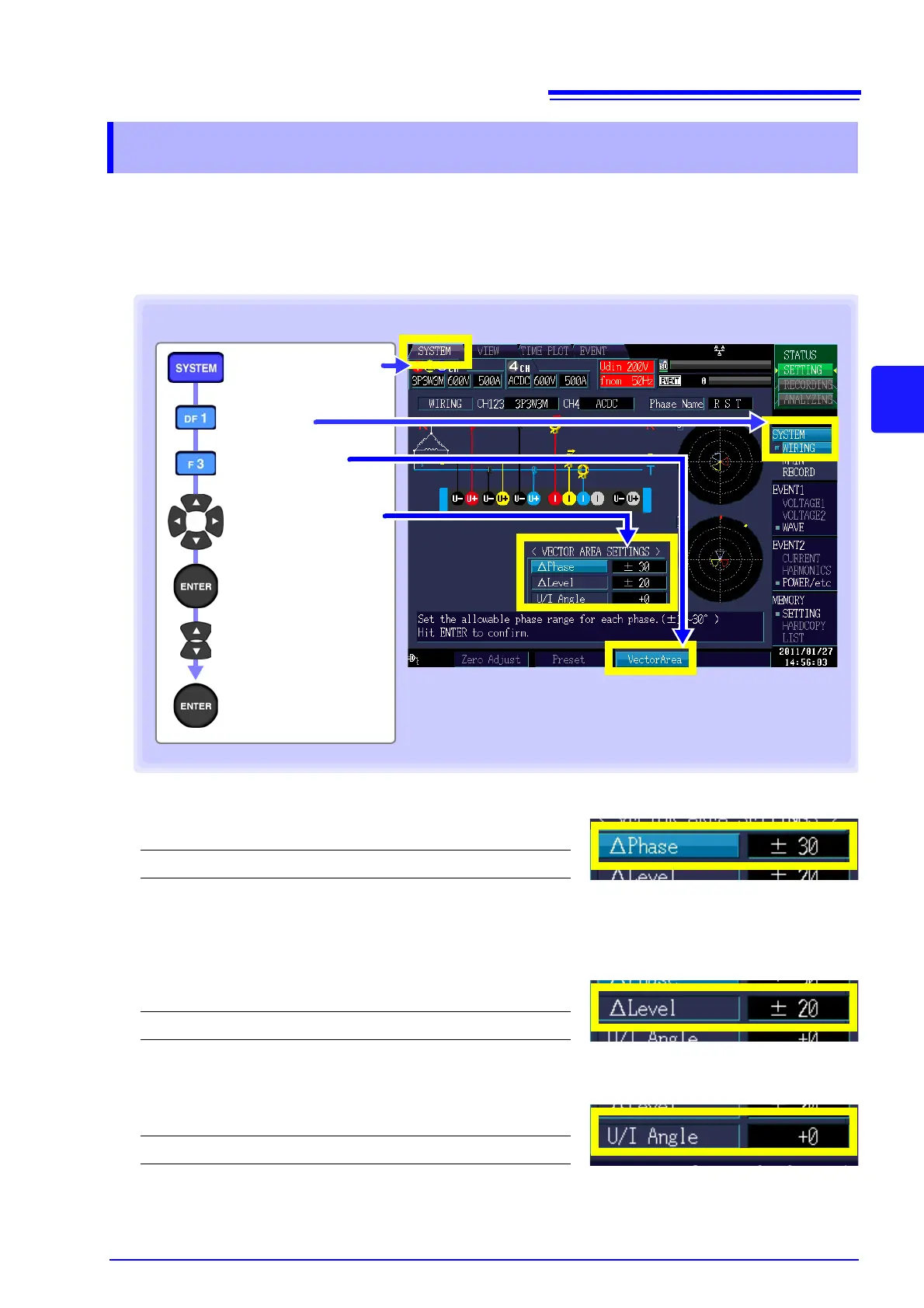
This section describes how to determine rough guidelines for verifying that the connection, range, and
nominal input voltage (Udin)
*
are correct. Changing settings causes corresponding changes in the area
and position of the fan-shaped areas on the vector diagram. The instrument can normally by used with
the default settings, but those settings can be changed if you wish to change the vector display area (tol-
erance level).
Phase
Sets the tolerance level for the phase value of each phase.
Level
Sets the tolerance level for the RMS value of each phase. The setting takes the form of (±1% to ±30%) of
the nominal voltage for voltage and CH1 for current.
U/I Angle
Sets the tolerance level for the current phase difference relative to the voltage.
*: The nominal input voltage (Udin), which is calculated from the nominal supply voltage using the trans-
former ratio, indicates the voltage that is actually input to the instrument.
4.4 Setting the Vector Area (Tolerance Level)
Setting Contents:( : Default setting)
±1 to ±30 ()
Setting Contents:( : Default setting)
±1 to ±30 (%)(±20)
Setting Contents:( : Default setting)
-60 to +60 () (0)
[WIRING]
[SYSTEM] screen
[VectorArea]
Key sequence for configuring settings
Select value to
change
Change the value
Accept setting
Select the setting
 Loading...