ELECTRICAL COMPONENTS
- 305 -
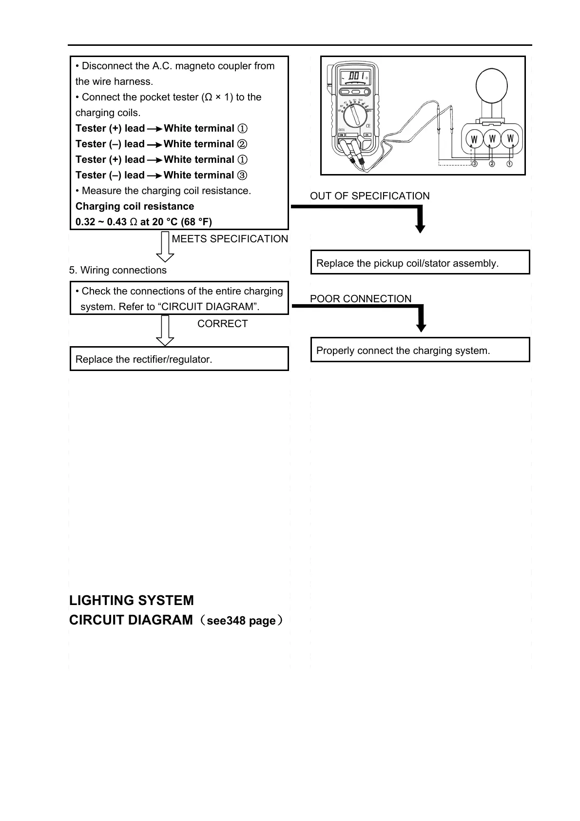
• Disconnect the A.C. magneto coupler from
the wire harness.
• Connect the pocket tester (Ω × 1) to the
charging coils.
Tester (+) lead
White terminal ①
Tester (–) lead
White terminal ②
Tester (+) lead White terminal ①
Tester (–) lead
White terminal ③
• Measure the charging coil resistance.
Charging coil resistance
0.32 ~ 0.43 Ω at 20 °C (68 °F)
MEETS SPECIFICATION
5. Wiring connections
• Check the connections of the entire charging
system. Refer to “CIRCUIT DIAGRAM”.
CORRECT
Replace the rectifier/regulator.
LIGHTING SYSTEM
CIRCUIT DIAGRAM
(see348 page)
OUT OF SPECIFICATION
Replace the pickup coil/stator assembly.
POOR CONNECTION
Properly connect the charging system.
 Loading...