GENERAL INFORMATION
- 22 -
2. Count the number of lines between the numbered sleeve mark and the edge of the thimble. Each
sleeve mark equals 0.025 in.
3. Read the thimble mark that aligns with the sleeve line. Each thimble mark equals 0.01 in.
NOTE
If a thimble mark does not align exactly with the
sleeve line, estimate the amount between the
lines. For accurate readings in ten-thousandths
of an inch (0.0001 in), use a vernier inch
micrometer.
4. Add the readings from Steps 1-3.
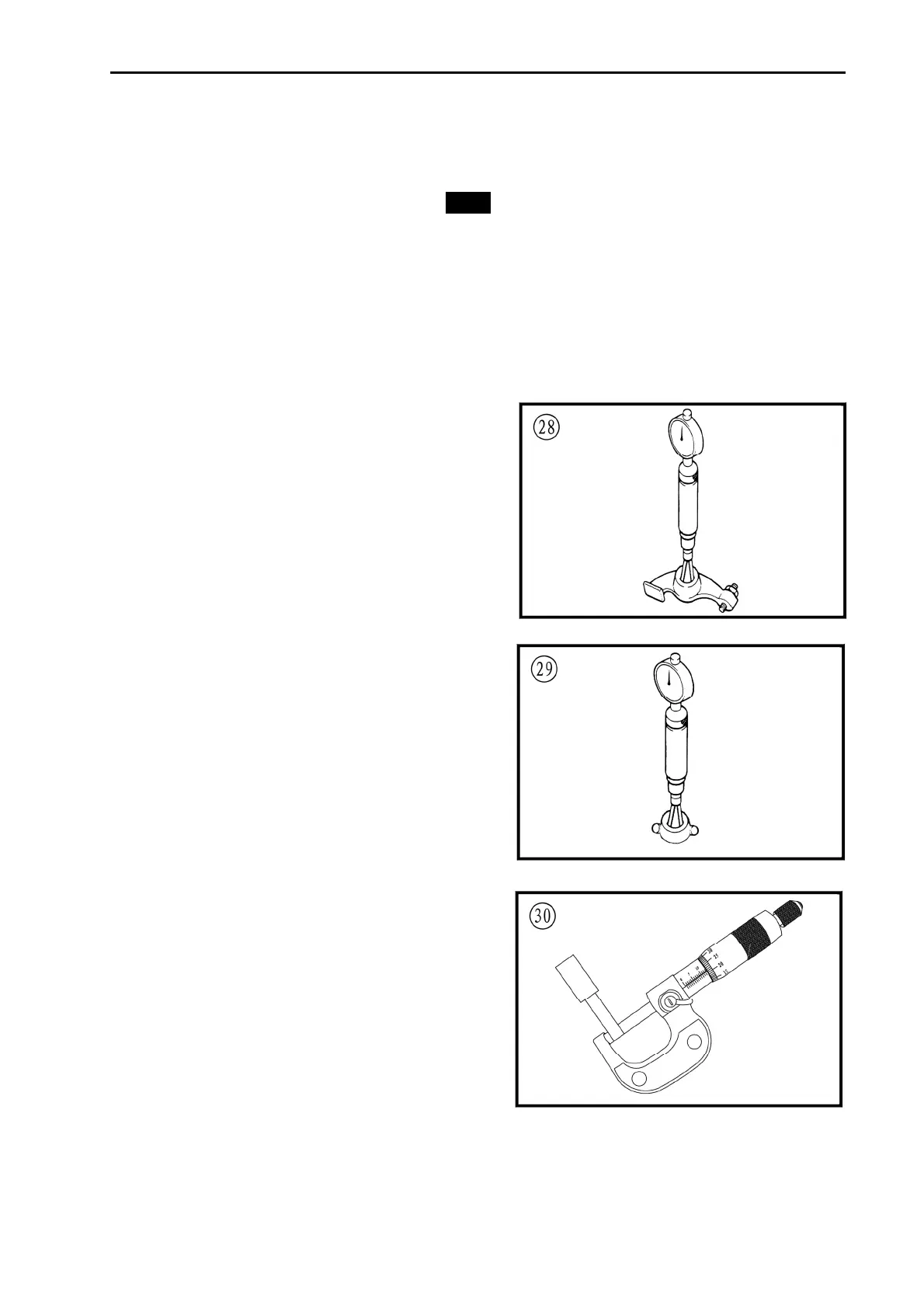
Telescoping and Small Bore Gauges
Use telescoping gauges (Figure 28) and small
bore gauges (Figure 29) to measure bores. Neither
gauge has a scale for direct readings. Use an outside
micrometer to determine the reading.
To use a telescoping gauge, select the correct
size gauge for the bore. Compress the movable post
and. Care fully insert the gauge into the bore. Carefully
move the gauge in the bore to make sure it is centered.
Tighten the knurled end of the gauge to hold the
movable post in position. Remove the gauge and
measure the length of the posts. Telescoping gauges
are typically used to measure cylinder bores.
To use a small bore gauge, select the correct size
gauge for the bore. Carefully insert the gauge into the
bore. Tighten the knurled end of the gauge to carefully
expand the gauge fingers to the limit within the bore.
Do not over tighten the gauge because there is no
built-in release. Excessive tightening can damage the
bore surface and damage the tool. Remove the
gauge and measure the outside dimension (Figure
30). Small bore gauges are typically used to
measure valve guides.
Dial Indicator:
A dial indicator (Figure 31) is a gauge with a dial
face and needle used to measure variations in
dimensions and movements. Measuring brake rotor
runout is a typical use for a dial indicator.
 Loading...