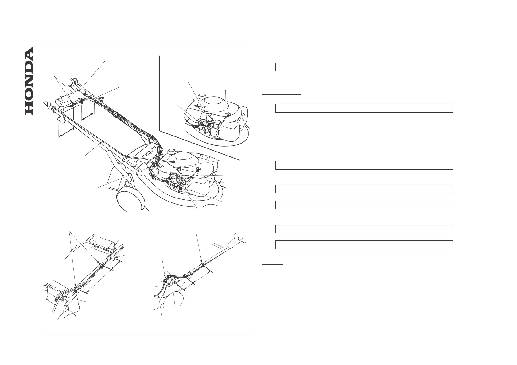
15.4 Wire / Harness routing
[1] CONTROL BOX (electrical starter type only)
See ch. 16.1 for wire harness connection.
[2] MAIN WIRE HARNESS (electrical starter type only)
HRD535/K1/K2
[3] OIL FILLER TUBE
Route the all wire harnesses between the oil filler tube and crankcase.
[4] CHARGING COIL WIRE
[5] IGNITION COIL WIRE
[6] STARTER MOTOR
HRD536/K1/K2
[7] OIL FILLER TUBE
Route the charging coil and ignition coil wires between the oil filler tube and crankcase.
[8] HANDLE JOINT KNOB
[9] WIRE BAND
Clamp wire harness and all control cables to handle.
[10] CABLE CLAMP
Clamp shift cable (S type only) and wire harness.
[11] RECOIL STARTER ROPE
[12] WIRE BAND
Clamp wire harness to handle.
[13] DISCHARGE GUARD
Route all cables and wire harness clear from edge of discharge guard.
HRA536
[14] WIRE BAND (3)
[15] SHIFT CABLE
[16] THROTTLE CABLE
[17] ROTOSTOP CABLE
- 111 -
HRA536 - HRD535 - HRD536
[1]
[2]
[3]
[4]
[5]
[4]
[5]
[6]
[7]
[8]
[9]
[10]
[11]
[12]
[13]
[17]
[14]
[15]
[16]
170 mm
170 mm
200 mm
350 mm
280 mm
70-80mm
HRD535/K1/K2
HRD536/K1/K2
HRA536
- HANDLE / CONTROL LEVERS
 Loading...