8.2 Control assembly
a. Removal / Installation
Petrol is highly flammable and explosive. If ignited,
petrol can burn you severely.
When draining petrol:
- Drain petrol into a approved container.
- Keep sparks and flames away, and do not smoke.
- Wipe up spills immediately.
NOTE:
It is not necessary to remove the engine.
1. Drain the petrol from the carburetor and fuel tank.
2. Remove the fuel tank (ch. 7.1)
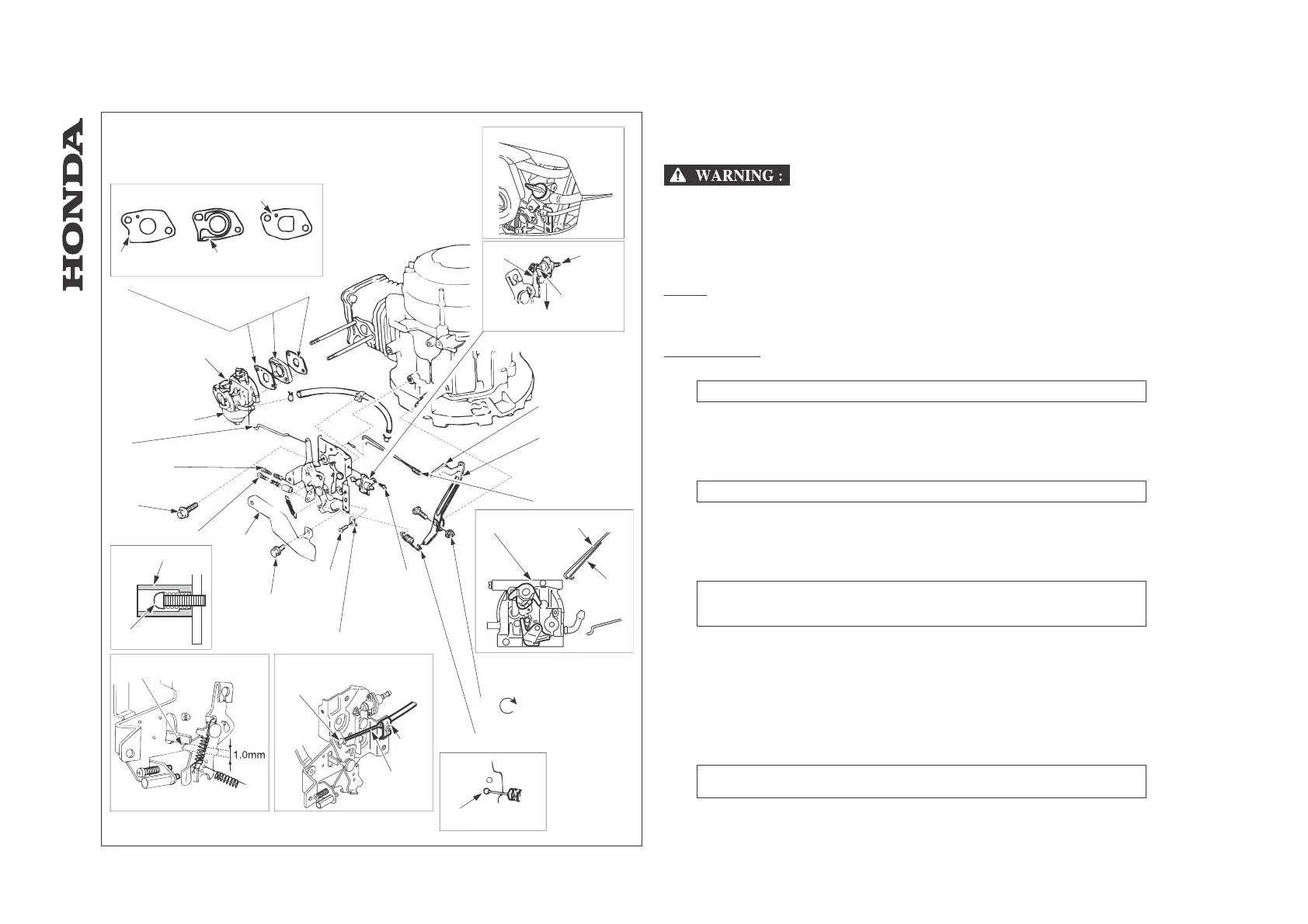
HRD535/K1/K2
[1] CARBURETOR
DISASSEMBLY / REASSEMBLY: ch. 8.3
[2] GASKET
[3] INSULATOR
[4] INSULATOR GASKET
[5] GASKETS / INSULATOR
INSTALLATION: Note the installation direction
[5]-1 GASKET
[5]-2 INSULATOR
[5]-3 INSULATOR GASKET
[6] FUEL SHUT-OFF VALVE
INSTALLATION: Insert the shaft of the valve to the groove of the lever. Connect the fuel
tube as shown.
INSPECTION: ch. 8.2b
[6]-1 LEVER
[6]-2 FROM FUELTANK
[6]-3 SHAFT
[6]-4 TO CARBURETOR
[7] GOVERNOR ROD
[8] GOVERNOR ARM
[9] ANTI-SURGE SPRING
INSTALLATION: Hook the ends through the small holes in the governor arm and
carburetor throttle lever.
[9]-1 GOVERNOR ROD
-55-
HRA536 - HRD535 - HRD536
[1]
[2]
[3]
[4]
[5]
[5]-1
[5]-2
[5]-3
[6]
[6]-1
[6]-2
[6]-3
[6]-4
[7]
[8]
[9]
[9]-1
[9]-2
[9]-3
[10]
[11]
[11]-1
[11]-2
[12]
[13]
[13]-1
[13]-2
[13]-3
[14]
[15]
[16]
[17]
[17]-1
[17]-2
[18]
[19]
[20]
[21]
HRD535
HRD535K1/K2
HRD535K1/K2
HRD535
[13]-3
10
- IGNITION COIL / CONTROL ARM / CARBURETOR
 Loading...