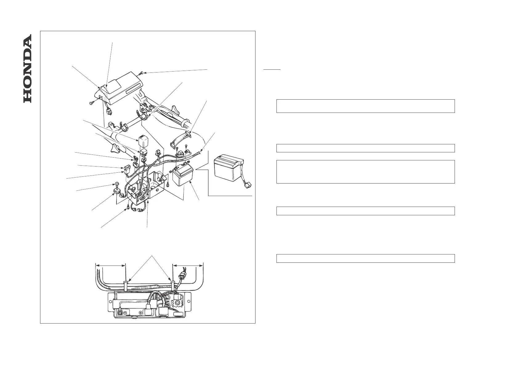
16. CONTROL BOX
16.1 Control box
a. Disassembly / Reassembly
NOTE:
HRD536 shown.
HRD535 is similar.
[1] CONTROL PANEL
[2] COMBINATION SWITCH
REMOVAL / INSTALLATION: ch. 16.2a
INSPECTION: ch. 16.2b
[3] SPECIAL SCREW,6x12mm(2)
[4] WIRE BAND (2)
[5] BATTERY BAND
[6] WIRE HARNESS
ROUTING: ch. 15.4
[7] BATTERY
REMOVAL: Disconnect the negative terminal first, then positive.
INSTALLATION: Connect the positive terminal first, then negative with care not to short
the battery terminals.
INSPECTION: ch. 16.3
[8] CONTROL BOX
[9] SCREW,6x10mm
[10] REGULATOR / RECTIFIER
INSPECTION: ch. 16.4
[11] SCREW,6x30mm
[12] FUSE 1 A
[13] FUSE HOLDER
[14] SPARE FUSE
[15] STARTER MOTOR RELAY
INSPECTION: ch. 16.4
[16] HOLDER RUBBER
[17] WIRE BAND
- 114 -
HRA536 - HRD535 - HRD536
[1]
[2]
[3]
[4]
[5]
[6]
[7]
HRD535/K1
[8]
[9]
[10]
[11]
[12]
[13]
[14]
[15]
[16]
[17]
170 mm
170 mm
- CONTROL BOX
 Loading...