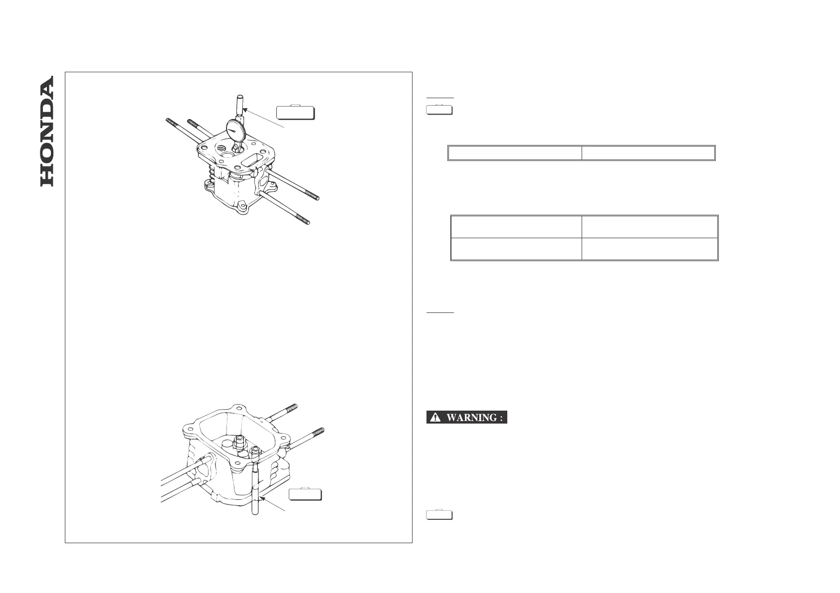
VALVE GUIDE I.D.
NOTE:
Ream the valve guides to remove any carbon deposits before measuring.
[1] VALVE GUIDE REAMER ..............................................07984-2000001
Measure and record each valve guide I.D.
Service limit IN/EX: 5.572 mm
Replace the valve guide if they are over the service limit.
STEM-TO-GUIDE CLEARANCE
Subtract each valve stem O.D. from the corresponding guide I.D. to obtain the
stem-to-guide clearance.
Standard
IN: 0.020 - 0.044 mm
EX: 0.060 - 0.087 mm
Service limit
IN: 0.10 mm
EX: 0.13 mm
If the stem-to-guide clearance exceeds the service limit, determine if the new guide with
standard dimensions would bring the clearance within tolerance.
If so, replace any guide as necessary and ream to fit. If the stem-to-guide clearance
exceeds the service limit with new guides, replace the valves as well.
NOTE:
The intake valve guide cannot be disassembled on model HRD535 (E/N ~
8189912).
Recondition the valve seats whenever the valve guides are replaced.
10.4 Valve guide replacement
1. Chill the replacement valve guides in the freezer section of a refrigerator for about an
hour.
2. Use hot plate or oven to heat the cylinder head evenly to 150° C (330° F).
Check the temperature with a temperature indicating stick (available at welding
supply stores) or equivalent.
To avoid burns, use heavy gloves when handling the heated cylinder.
CAUTION:
•
Do not use a torch to heat the cylinder head; warpage of the cylinder head may result.
•
Do not get the cylinder head hotter than 150° C (300° F); excessive heat may loosen the
valve seats.
3. Remove the heated cylinder head from hot plate and support it with wooden blocks.
Drive the valve guides out of the head from the combustion chamber side.
[2] VALVE GUIDE DRIVER ..............................................07942 - 8920000
-69-
HRA536 - HRD535 - HRD536
- CYLINDER HEAD / VALVES
[1]
S.TOOL
S.TOOL
[2]
S.TOOL
S.TOOL
 Loading...