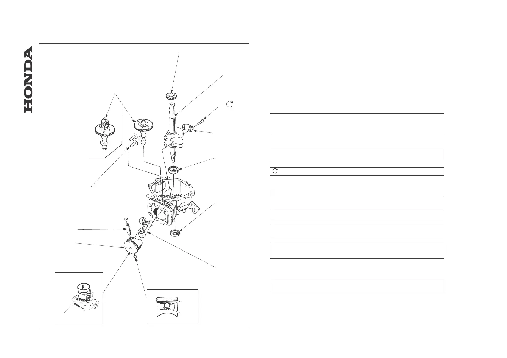
12. CRANKSHAFT / PISTON / CYLINDER
12.1 Disassembly / Reassembly
1. Remove the engine (ch. 5) then remove the following:
- Air cleaner and muffler (ch. 6).
- Fuel tank (ch. 7).
- Control arm and carburetor (ch. 8).
- Flywheel and starter motor (ch. 9).
- Cylinder head (ch. 10).
- Oil pan (ch. 11).
[1] CAMSHAFT
VALVE TIMING ADJUSTMENT: ch. 12.1
INSPECTION: ch. 12.2
[A] HRD535/K1/K2 Q type - HRA536
[B] HRD535/K1 except Q type - HRD536/K1/K2
[2] TIMING GEAR
[3] CRANKSHAFT
REASSEMBLY: Push in firmly until contact is made with the bearing surface.
Be careful not to damage the oil seal lip.
[4] CONNECTING ROD SCREW
TIGHTNING TORQUE: 12 N.m
[5] LOWER CAP
[6]
BALL BEARING (HRD535/K1/K2: 62/22, HRA536 - HRD536/K1/K2: 6205)
REPLACEMENT: ch. 12.1
[7]
OIL SEAL (HRD535/K1/K2: 22x35x6mm,
HRA536 - HRD536/K1/K2: 25x38x7mm
REASSEMBLY: ch. 12.1
[8] CONNECTING ROD
REASSEMBLY: Make sure that the longer end mark “A” facing side of the piston head
with the “+” mark.
[9] PISTON PIN SNAP RING (2)
REASSEMBLY: Install by setting one end of snap ring in the piston cut-out, holding the
other edge with long-nosed pliers, and rotating the snap ring in. Do not align the end gap
of the snap ring with the cut-out in the piston pin bore.
[9]-1 SNAP RING
[9]-2 CUT-OUT
[10] PISTON
REASSEMBLY: Install the piston using a piston slider (commercially available) and
facing the “+” mark toward the push rods.
[10]-1 PISTON SLIDER ...............................................commercially available
[11] “+” MARK
[12] PISTON PIN
[13] VALVE LIFTER (2)
-75-
HRA536 - HRD535 - HRD536
[1]
[
]
[3]
[4]
[5]
[6]
[7]
[8]
[9]
[9]-1
[9]-2
[10]
[10]-1
[11]
[12]
[13]
[A]
[B]
12
- OIL PAN / DRIVE SHAFT / GOVERNOR
 Loading...