4. BLADE / ROTOSTOP
4.1 How the Rotostop works
HRD535K1: 8106640 ~ , HRD536K1: 8107480 ~
HRD535K2 - HRD536K2
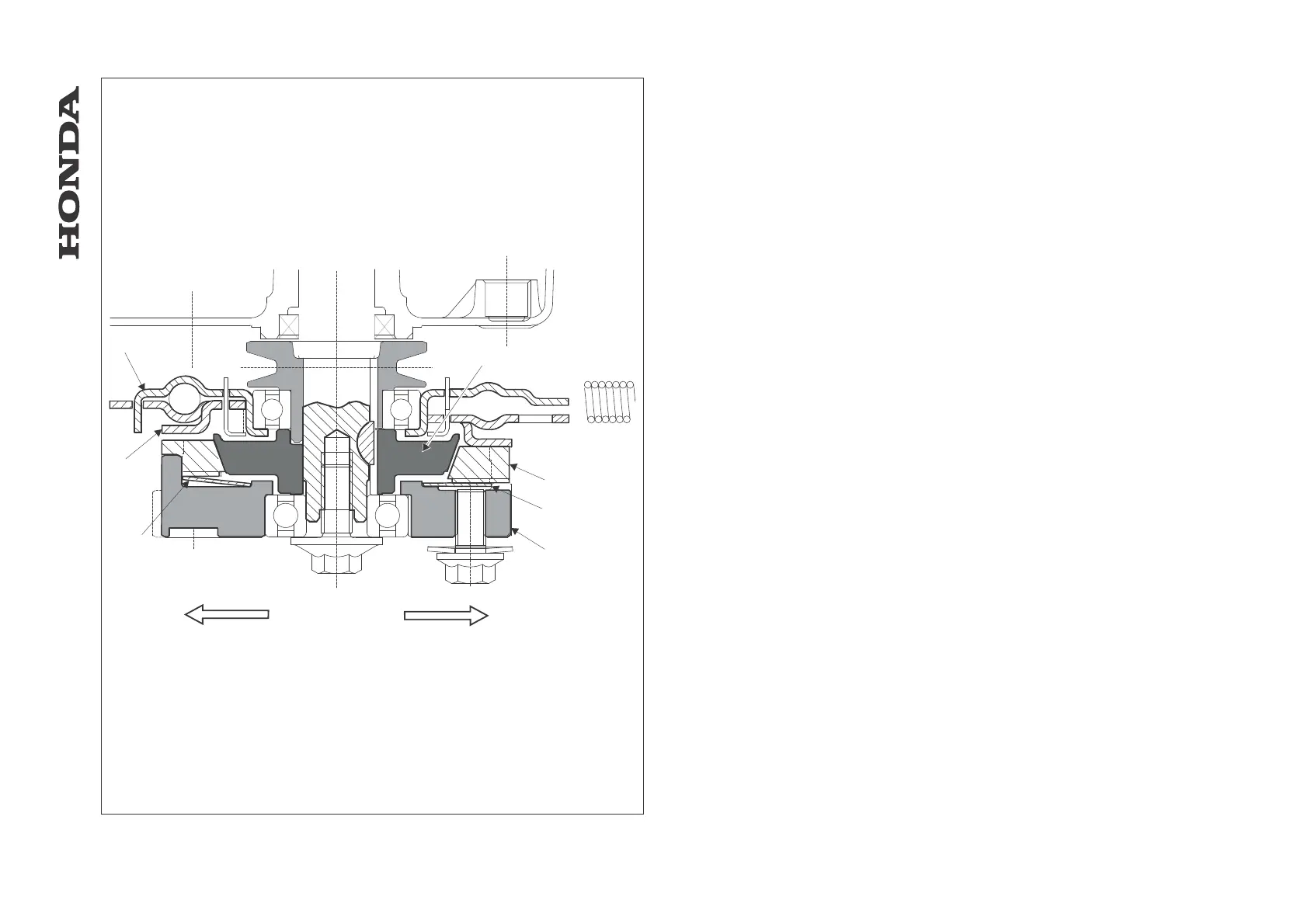
Rotostop lever engaged (left-hand section of the drawing)
1. The clutch control plate [1] pivots anti-clockwise.
2. The brake anchor plate [2] rises and moves away from the upper part of the lining [3].
3. The clutch spring [4] pushes the lining [3] (female cone) against the clutch cone [5]
(male cone).
4. The lining [3] then drives the blade holder [6] through detents located around the edge
of the lining.
5. The blade starts to rotate.
Rotostop lever released (right-hand section of the drawing)
1. The Rotostop return spring pivots the control plate [1] clockwise.
2. The brake anchor plate [2] drops and pushes against the upper part of the lining [3]. At
the same time, the lining [3] is pushed downwards by the brake anchor plate [2],
moving it away from the clutch cone [5].
3. The blade stops.
[1] CLUTCH CONTROL PLATE
[2] BRAKE ANCHOR PLATE
[3] LINING
[4] CLUTCH SPRING
[5] CLUTCH CONE
[6] BLADE HOLDER
[7] ROTOSTOP LEVER ENGAGED
[8] ROTOSTOP LEVER RELEASED
-32-
HRA536 - HRD535 - HRD536
[1]
[2]
[4]
[4]
[5]
[3]
[6]
[7]
[8]
- BLADE / ROTOSTOP
 Loading...