ELECTRIC CONTROL FUNDAMENTALS
ENGINEERING MANUAL OF AUTOMATIC CONTROL
109
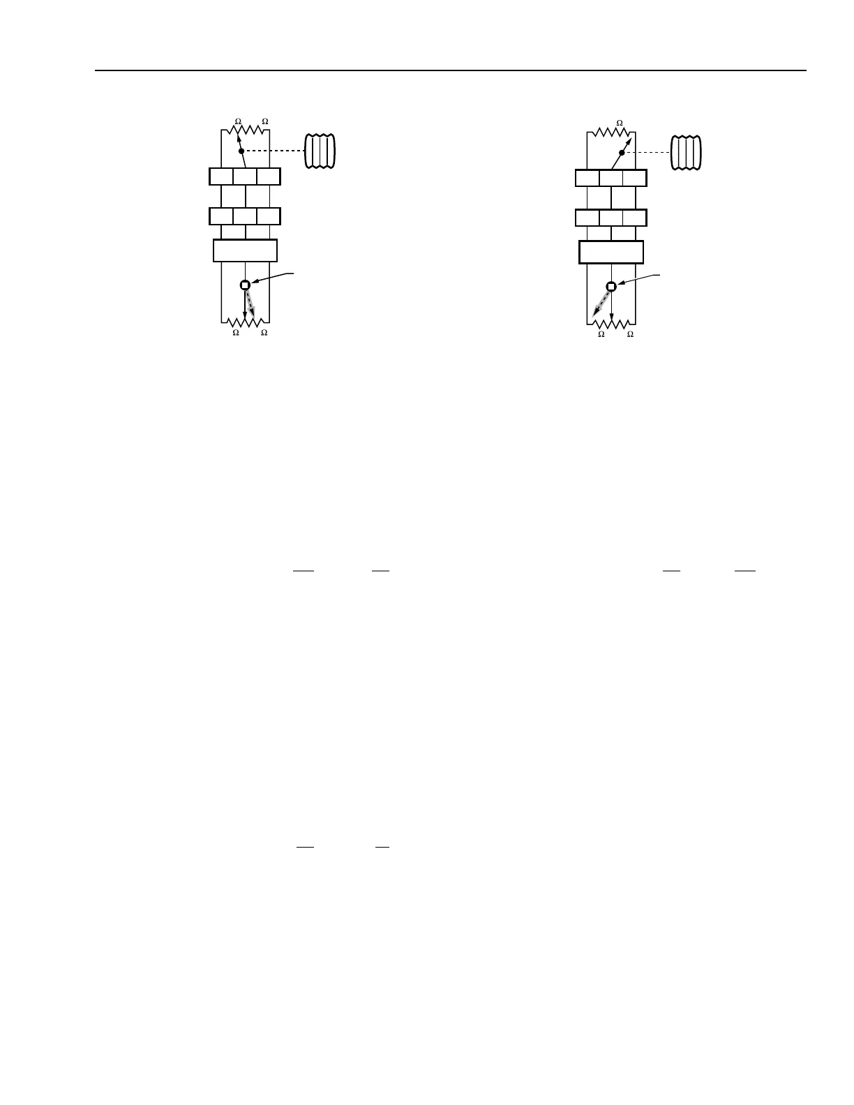
Fig. 21. Bridge Circuit on Increase
in Controlled Variable.
The unbalance causes the electronic relay to trigger the left
triac, energize the ccw motor winding, and drive the actuator
drive shaft toward closed. Since half of the 70-ohm unbalance
has to go on each side of the bridge to rebalance the circuit, the
feedback potentiometer will move 35 ohms to the right. The
table then appears as follows:
Left Leg Right Leg
Controller potentiometer 35 105
Feedback potentiometer 105 35
Total 140 140
When the feedback potentiometer reaches the new position
(shown dotted) the bridge is rebalanced, the left triac turns
off, and the actuator drive shaft stops in the new position
(25 percent open).
BRIDGE CIRCUIT ON DECREASE IN CONTROLLED VARIABLE
Figure 22 illustrates the bridge circuit in an unbalanced
condition on a decrease in the controlled variable. The controller
potentiometer wiper R has moved all the way to the B end and
the feedback potentiometer wiper is at the center. This causes
an unbalance of 140 ohms (210 – 70) in the left leg as shown:
Left Leg Right Leg
Controller potentiometer 140 0
Feedback potentiometer 70 70
Total 210 70
Fig. 22. Bridge Circuit on Decrease
in Controlled Variable.
The unbalance causes the electronic relay to trigger the right
triac (Fig. 19), energize the cw motor winding, and drive the
actuator drive shaft toward open. Since half of the 140-ohm
unbalance has to go on each side of the bridge to rebalance the
circuit, the feedback potentiometer will move 70 ohms to the
left. The table then appears as follows:
Left Leg Right Leg
Controller potentiometer 140 0
Feedback potentiometer 0 140
Total 140 140
When the feedback potentiometer reaches the new position
(shown dotted) the bridge is rebalanced, the right triac turns
off, and the actuator drive shaft stops in the new position
(100 percent open).
BRIDGE CIRCUIT WITH LIMIT CONTROLS
Limit controls are commonly used to prevent the discharge
air temperature of a central fan system from becoming too low
or too high. Figures 23 and 24 illustrate limit controls in a
heating application. These controls add resistance in the bridge
circuit and drive the actuator toward the open position if a low-
limit condition is approached (Fig. 23) or toward the closed
position if a high-limit condition is approached (Fig. 24).
Limit controllers can have either a 140- or a 280-ohm
potentiometer. The 140-ohm potentiometer can drive an actuator
only half-way open (or closed) since it adds resistance into one
leg of the bridge but does not subtract resistance from the other
leg. If 100 percent control is required from a limit controller, a
280-ohm potentiometer device should be used. The following
examples are for limit controls with 140-ohm potentiometers.
W
ELECTRONIC
RELAY
RB
WRB
DRIVE
SHAFT
CONTROLLER
POTENTIOMETER
35
105
70 70
SENSING
ELEMENT
OPEN
CLOSE
FEEDBACK
POTENTIOMETER
C2522
W
ELECTRONIC
RELAY
RB
WRB
DRIVE
SHAFT
CONTROLLER
POTENTIOMETER
140
70 70
SENSING
ELEMENT
OPEN
CLOSE
FEEDBACK
POTENTIOMETER
C2523
 Loading...


