PNEUMATIC CONTROL FUNDAMENTALS
ENGINEERING MANUAL OF AUTOMATIC CONTROL
85
N.O.
VALVE
HEATING COIL
C2380
DISCHARGE
AIR
B S M
M
BP
P
B S M
M
SENSOR
RETURN AIR
SENSOR
PRIMARY
CONTROLLER (DA)
LOW-LIMIT
CONTROLLER (DA)
LOW-PRESSURE
SELECTOR
RELAY
EXH
— The controller must be located where the condition it
measures is uniformly affected by changes in position of
the multiple valves. If not, the application requires more
than one controller.
A direct- or reverse-acting signal to a three-way mixing or
diverting valve must be selected carefully. Figure 58 shows that
the piping configuration determines the signal required.
cooling valve is closed. As the temperature rises, the branchline
pressure increases and the heating valve starts to close. At
48 kPa branchline pressure, the heating valve is fully closed.
If the temperature continues to rise, the branchline pressure
increases until the cooling valve starts to open at 55 kPa. The
temperature must rise enough to increase the branchline pressure
to 90 kPa before the cooling valve will be full open. On a drop
in temperature, the sequence is reversed.
Valves with positive positioners ensure tight close-off of the
heating valve at 48 kPa branchline pressure, and delay opening
of the cooling valve until 55 kPa branchline pressure is reached.
Positive positioners prevent overlapping caused by a variation
in medium pressure, a binding valve or damper, or a variation
in spring tension when using spring ranges for sequencing.
A greater deadband can be set on the positioners to provide a
larger span when no energy is consumed. For example, if the
positioners are set for 13 to 48 kPa on heating and 90 to 124 kPa
on cooling, no energy is used when the controller branchline
pressure is between 48 and 90 kPa. The positioners can also be
set to overlap (e.g., 30 to 60 and 48 to 80 kPa) if required.
Valve and damper actuators without positioners have various
spring ranges. To perform the sequencing application in Figure
59 without positioners, select a heating valve actuator that has
a 13 to 48 kPa spring range and a cooling valve actuator that
has an 55 to 90 kPa spring range. Although this method lessens
precise positioning, it is usually acceptable in systems with
lower pressure differentials across the valve or damper and on
smaller valves and dampers .
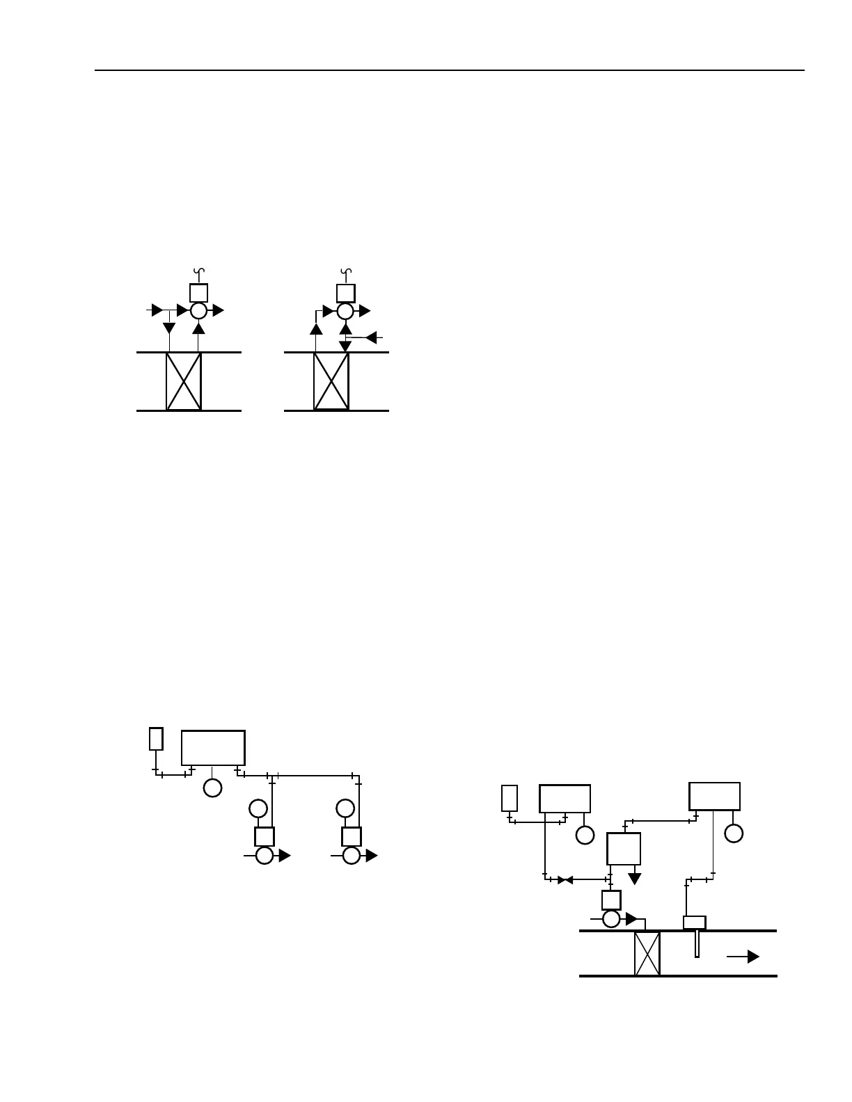
LIMIT CONTROL
Figure 60 shows a sensor-controller combination for space
temperature control with discharge low limit. The discharge
low limit controller on a heating system prevents the discharge
air temperature from dropping below a desired minimum.
Fig. 59. Pneumatic Sequencing of Two Valves
with Positive Positioning Actuators.
When the temperature is so low that the controller calls for
full heat, the branchline pressure is less than 20 kPa. The
normally open heating valve is open and the normally closed
HOT WATER
SUPPLY
HOT WATER
SUPPLY
DIRECT-
ACTING
SIGNAL
THREE-WAY
MIXING VALVE
HOT WATER
RETURN
HOT WATER
RETURN
THREE-WAY
MIXING VALVE
REVERSE-
ACTING
SIGNAL
C2377
HOT WATER COIL
HOT WATER COIL
Fig. 58. Three-Way Mixing Valve
Piping with Direct Actuators.
SEQUENCE CONTROL
In pneumatic control systems, one controller can operate
several dampers or valves or several groups of dampers or valves.
For example, year-round air conditioning systems sometimes
require heating in the morning and evening and cooling in the
afternoon. Figure 59 shows a system in which a single controller
controls a normally open heating valve and normally closed
cooling valve. The cooling valve is set for an 55 to 90 kPa range
and the heating valve, for a 13 to 48 kPa range. The controller
operates the two valves in sequence to hold the temperature at the
desired level continually.
Fig. 60. Low-Limit Control (Heating Application).
LOW-PRESSURE
SELECTOR
RELAY
M
M
M
S M B
M P M P
POSITIVE
POSITIONING
ACTUATORS
N.C. COOLING
VALVE
50-90 kPa
N.O. HEATING
VALVE
13-48 kPa
SENSOR
DA
CONTROLLER
C4224
 Loading...


