MICROPROCESSOR-BASED/DDC FUNDAMENTALS
141ENGINEERING MANUAL OF AUTOMATIC CONTROL
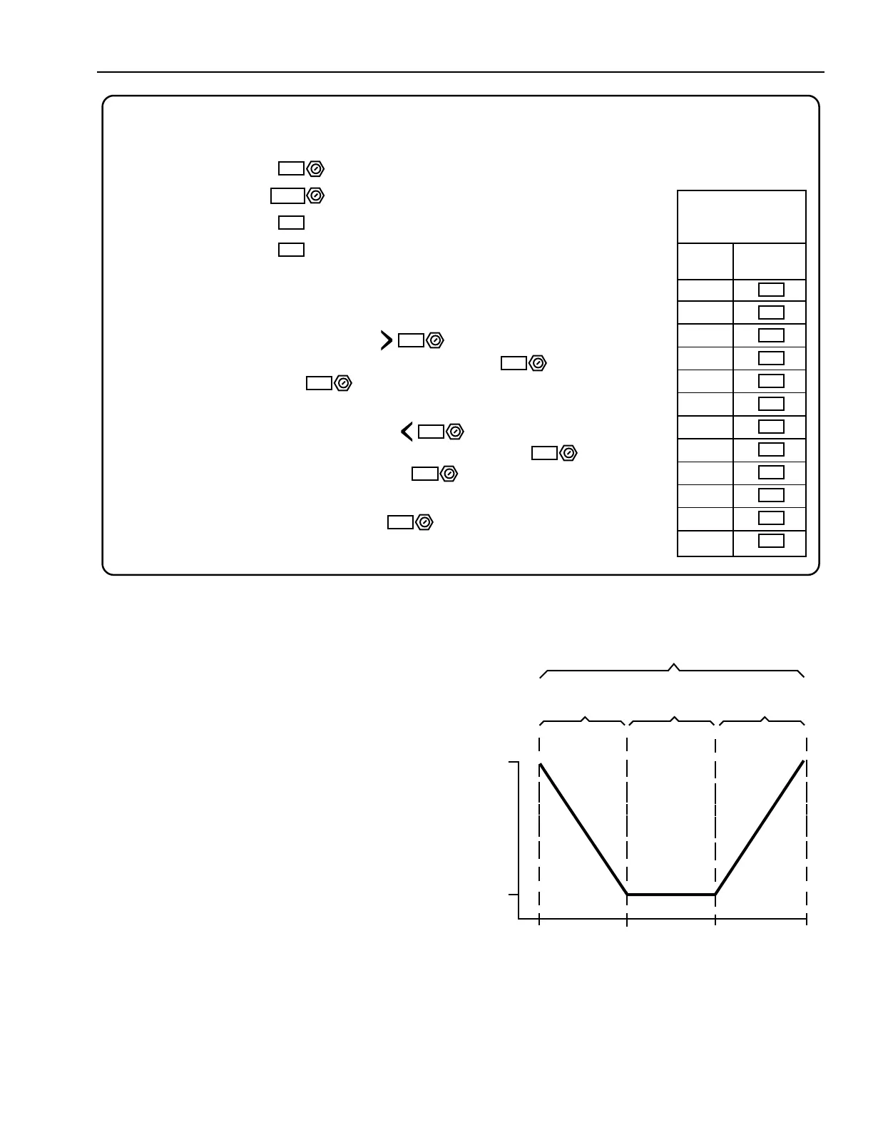
Fig. 10. Dynamic Data Display Example
Load reset works best when the number of monitored loads
are between 2 and 30. If any monitored load is undersized or
stays in full cooling for any reason, reset will not occur. See
the Air Handling Systems Control Applications section and the
Chiller, Boiler, and Distribution System Control Applications
section for other load reset examples.
Zero Energy Band
The zero energy band (Fig. 11) program provides a dead
band where neither heating nor cooling energy is used. This
limits energy use by allowing the space temperature to float
between minimum and maximum values. It also controls the
mixed-air dampers to use available outdoor air if suitable for
cooling. On multizone fan systems with simultaneous heating
and cooling load capability, zone load reset controls the hot
and cold deck temperature setpoints.
Fig. 11. Zero Energy Band.
FULL
ON
FULL
OFF
21
23
24 25.5
TYPICAL SPACE TEMPERATURE RANGE (°C)
HEATING
REGION
ZERO ENERGY
BAND
COOLING
REGION
HEATING COOLING
VENTILATION
ONLY
C4314
TOTAL COMFORT RANGE
M15138
AUTO
8
68
73
74
77
79
70
64
69
79
74
74
74
7
36
95
4.0
6
11
MANUAL SETPOINT
AUTO-MANUAL SELECTOR
CURRENT LEAVING WATER TEMPERATURE
CURRENT CHILLER LOAD (% AMPS)
AUTOMATIC MODE SEQUENCE OF CONTROL
ANYTIME ANY AHU CHW VALVE IS % OPEN, THE CHW
TEMPERATURE SETPOINT WILL BE DECREMENTED DEGREES,
BUT TO NO LESS THAN DEGREES.
ANYTIME ALL AHU CHW VALVES ARE % OPEN, THE
CHW TEMPERATURE SETPOINT WILL BE INCREMENTED
DEGREES, BUT TO NO GREATER THAN DEGREES.
THIS PROGRAM EXECUTES EVERY MINUTES.
CHILLED WATER TEMPERATURE SETPOINT CONTROL
CURRENT VALUE
CHILLED WATER
VALVES
AHU
#
%
OPEN
1
2
3
4
5
6
7
8
9
10
11
12
80
0.2
0.2
 Loading...


