ENGINEERING MANUAL OF AUTOMATIC CONTROL
CHILLER, BOILER, AND DISTRIBUTION SYSTEM CONTROL APPLICATIONS
342
VARIABLE SPEED PUMPS
From the pump affinity laws (Table 3), pump power decreases
by the cube of the decreased speed, and flow decreases linearly
with speed; so at 80 percent flow, the power (kW) is down to
nearly 50 percent (80 percent cubed). Since many systems have
sharply reduced flow requirements at medium or low loads,
pump speed control can provide economical operation for most
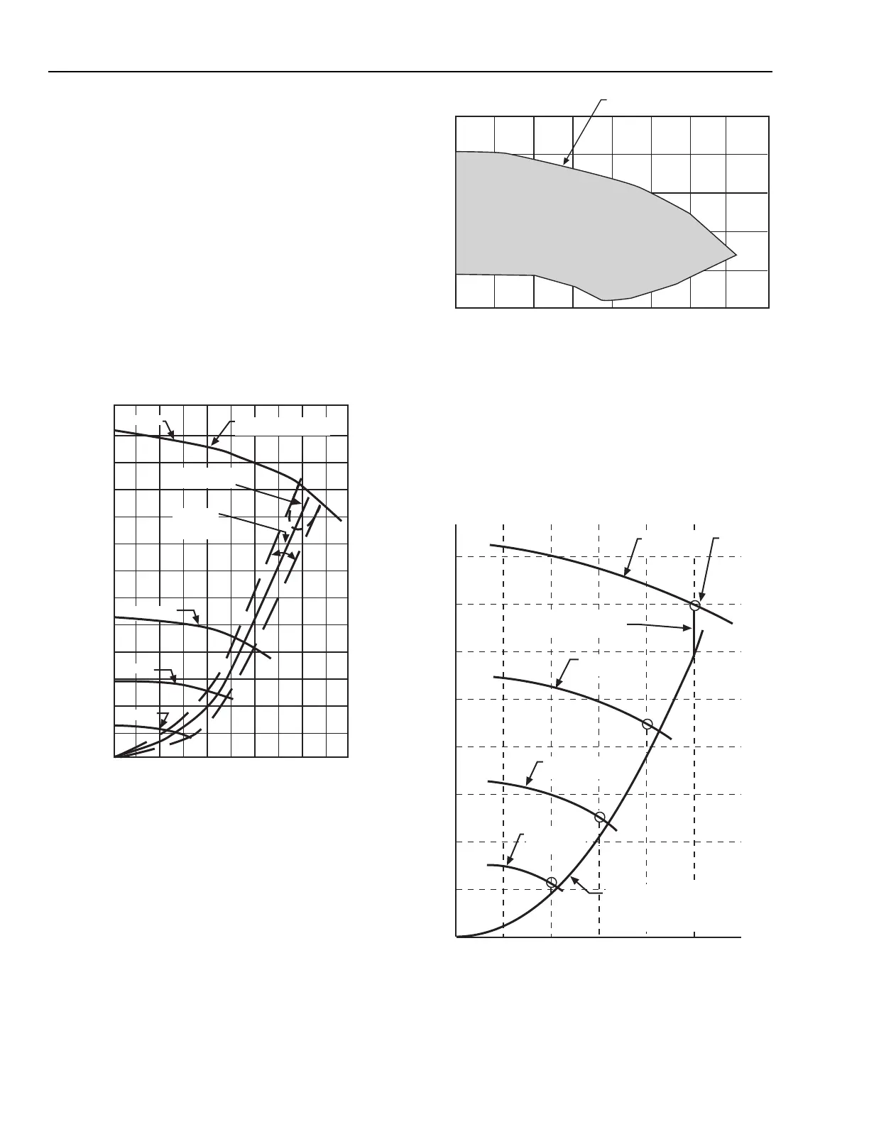
of the heating (or cooling) season. Figure 59 shows typical
performance at reduced speeds. The shaded area of Figure 60
shows the wide range of pressures and flows available from a
variable speed pump. Variable speed pumps are usually
controlled from a differential pressure sensor with either fixed
or load reset setpoints.
Control objectives of variable speed pumping systems in
networked digital control systems, is to keep the most demanding
load control valve full open by varying the pump speed.
Fig. 60. Typical Variable Speed
Pump Performance Range.
Table 4 and Figure 61 show the Figure 58 system with all the
control valves remaining full open and the load controlled by
varying the pump speed. This is the ideal system wherein the
loads of all AHUs vary in unison and the pump speed is
controlled to satisfy the valve with the greatest demand. This
is usually accomplished via differential pressure control,
automatically reset.
Fig. 59. Pump Performance and
Efficiency at Various Speeds.
Fig. 61. Ideal Variable Speed Pump Control.
150
0 6.25 12.5 18.75 25 31.25
0
15
30
45
60
75
90
105
120
135
165
180
195
TOTAL PRESSURE (kPa)
FLOW (L/s)
C4094
1750 RPM
REGION OF BEST
EFFICIANCY
BEST
EFFICIANCY
AREA
1150 RPM
850 RPM
550 RPM
PUMP HEAD-CAPACITY
CURVES
FLOW (L/s)
TYPICAL RANGE OF PERFORMANCE
FOR VARIABLE SPEED PUMP
TOTAL PRESSURE (kPa)
300
240
180
120
60
0
0
6.25
12.5
18.75
25
31.25
37.5
43.75
C4095
1750 RPM
PUMP CURVE
SYSTEM CURVE FOR STATIC
ELEMENTS OF SYSTEM (CHILLER,
PIPING, FITTINGS, BALANCING
COCKS, COILS, STRAINERS, ETC.)
OPERATING
POINT
240
210
180
150
120
90
60
30
0
0 5 10 15 20 25
1400 RPM
PUMP CURVE
1050 RPM
PUMP CURVE
700 RPM
PUMP CURVE
FULL OPEN
CONTROL VALVE DROP
M15281
PRESSURE (kPa)
SYSTEM FLOW IN L/s
 Loading...


