ENGINEERING MANUAL OF AUTOMATIC CONTROL
CHILLER, BOILER, AND DISTRIBUTION SYSTEM CONTROL APPLICATIONS
315
THERMAL STORAGE CONTROL
GENERAL
Thermal storage is used to save heating or cooling for future
use. Typically enough storage is provided to meet the load
requirements for a 24-hour period. During the cooling season,
storage of low cost night time cooling can save energy and
demand charges and reduce the chilled water generating
equipment design size. During the heating season, storage of
rejected day time excess refrigeration heat or solar heat can be
used for night time heating loads. Storage may use a water
tank or ice bin for cooling and a water tank or thermal
conducting fluid for heat. The storage efficiency depends on
the amount of insulation and, in the case of water storage, on
minimizing the mixing of return water with storage water.
Mixing in water storage can be minimized by use of a segmented
container for storage (Fig. 24).
Primary control requirements are storage charge and storage
discharge at the proper times and rates. Storage charge, storage
discharge, and instantaneous cooling are the three basic control
modes. Combinations of the basic control modes may be
required to meet the load or predicted load. When the predicted
load is high, the chiller provides chilled water for both the
current load and for storage. When the predicted load occurs,
the stored cooling is added to the chiller output.
CONTROL MODES
The appropriate control mode depends on the load predicted
for next day, relative storage size, and relative costs of stored
and instantaneous cooling, including electrical demand rate
structures. The storage charging cycle is normally activated
when cooling generation cost is lowest, such as at night when
lower condenser water temperatures provide lower refrigeration
pressure and when lower time-of-day electric rates may be
applicable. The rate of charge should satisfy storage quantity
requirements within the limits of the time available.
Use of stored energy verses instantaneous cooling energy is
prioritized. When enough stored energy is available to satisfy
the load through the peak demand period of the next day, only
stored energy is used (storage priority). In this case, the charging
cycle is scheduled to start when low cost cooling is available.
The charging cycle is stopped when storage is sufficient for the
next days load or when the storage capacity is filled. The storage
discharge cycle is controlled to meet load conditions. If storage
capacity is not large enough for the next day, the chiller
supplements the use of stored cooling, as necessary. The control
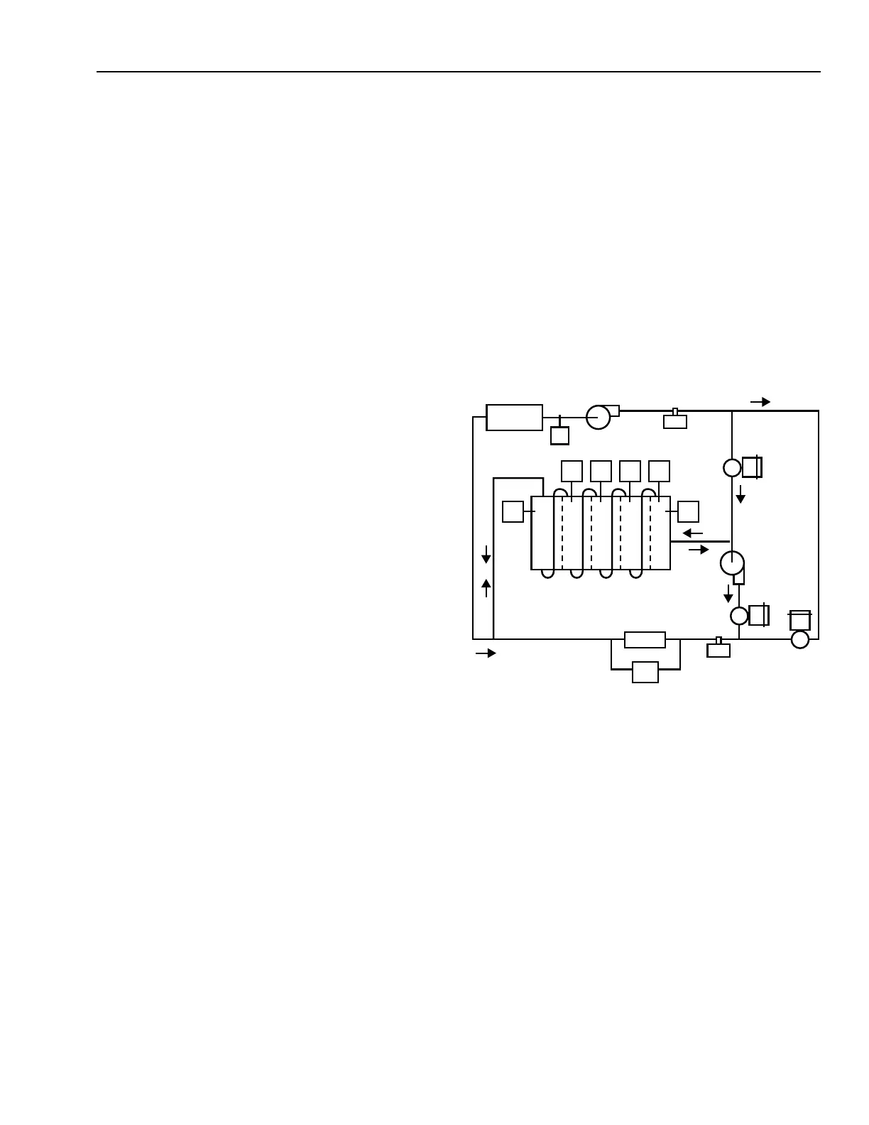
sequences for segmented chilled water storage (Fig. 24) are:
– Instantaneous Cooling Cycle: Pump P
1
is on and Pump
P
2
is off. Valves V
C
and V
D
are closed. Valve V
I
is
controlled by ∆P and T
1
controls chiller.
– Charging Cycle: Valves V
D
and V
I
are closed and V
C
is
controlled by T
6
to maintain the flow rate at F
1
. Pump
P
2
is off. T
1
controls chiller capacity to maintain 4.5°C
CHWS temperature. When the T
5
(A through E)
location,
representing the needs for the next day, reaches 4.5°C,
the charging cycle is stopped.
– Charging plus Instantaneous Cooling Cycle: Charging
cycle continues while V
I
is controlled from ∆P. Pump
P
2
is off. The flow through the storage is T
5E
to T
5A
.
– Discharge Cycle (enough storage for anticipated load):
Valves V
C
and V
I
are closed, chiller and Pump P
1
are
off, and Pump P
2
is on. Valve V
D
is controlled from ∆P.
– Discharge plus Instantaneous Cooling Cycle (not
enough storage for anticipated load): Pumps P
1
and P
2
are on, V
C
is closed. Chiller demand D
1
limits chiller
capacity while T
2
positions V
I
to maintain chilled water
supply temperature. ∆P throttles valve V
D
to provide
flow from storage.
Fig. 24. Segmented Chilled Water Storage.
The chiller takes priority when stored energy costs are larger
than instantaneous energy costs. Under these conditions the
only cooling stored is that required to reduce the anticipated
demand limit for the next day. Storage size and energy cost,
including demand charges, establish the control strategies for
this situation. The control objectives are to limit demand for
the billing period and to minimize energy costs. Chiller
discharge is controlled to meet load. The sequence of the control
is to run the charging plus instantaneous cooling cycle, then
stop charging when the quantity necessary to meet the
anticipated demand limit for the next day is stored.
CHILLER
D
1
F
1
T
5A
T
5B
T
5C
T
5D
T
5E
T
6
LOADS
V
C
P
1
T
1
N.O.
N.O.
N.O.
P
2
T
2
∆P
SEGMENTED STORAGE
C
C
C
D
D
D
V
D
V
I
I
= FLOW DIRECTION
C= CHARGING CYCLE
D= DISCHARGING CYCLE
I = INSTANTANEOUS COOLING
NOTE: NOT ALL CONTROLS ACTIVE FOR ALL SEQUENCES
C2693
 Loading...


