MICROPROCESSOR-BASED/DDC FUNDAMENTALS
135ENGINEERING MANUAL OF AUTOMATIC CONTROL
(IAQ), and/or building management functions. Changes in
control sequences can easily be accommodated through
software whether dictated by system performance or by changes
in the owner’s use of the facility.
COORDINATED MULTIFUNCTION
CAPABILITY
Although basic environmental control and energy
management operate as independent programs, it is best to have
them incorporated as an integrated program in order to provide
more efficient control sequences. For example, sensing the
temperatures of several zones to determine the average demand,
or the zone with the greatest demand for cooling, will provide
improved efficiency and control over merely sampling a
representative zone for a chiller reset program. An added feature
is that the sensors providing zone comfort control can serve a
dual function at no added cost. These benefits require controller-
to-controller communications which is discussed in the Building
Management System Fundamentals section.
PRECISE AND ACCURATE CONTROL
Proportional control has the inherent problem of offset. The
wider the throttling range is set for control stability, the greater
the offset. With the microprocessor-based controller, the offset
can easily be corrected by the simple addition of integral action.
For even more accurate control over a wide range of external
conditions, adaptive control algorithms, available in some
microprocessor-based controllers, can be employed. With
adaptive control, system performance automatically adjusts as
conditions vary. The need for manual fine tuning for seasonal
changes is eliminated. These items are discussed in the Control
Fundamentals section.
RELIABILITY
Digital controllers should be conservatively designed and
should incorporate self-checking features so they notify the
operator immediately if anything goes wrong. Input and output
circuits should be filtered and protected from extraneous signals
to assure reliable information to the processor.
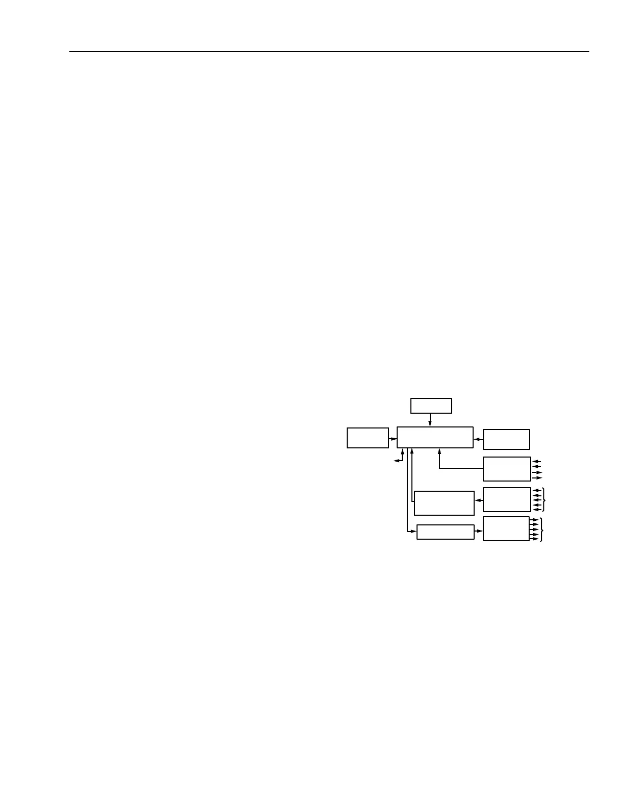
The basic elements of a microprocessor-based (or micro-
processor) controller (Fig. 3) include:
— The microprocessor
— A program memory
— A working memory
— A clock or timing devices
— A means of getting data in and out of the system
In addition, a communications port is not only a desirable feature
but a requirement for program tuning or interfacing with a
central computer or building management system.
Timing for microprocessor operation is provided by a battery-
backed clock. The clock operates in the microsecond range
controlling execution of program instructions.
Program memory holds the basic instruction set for controller
operation as well as for the application programs. Memory size
and type vary depending on the application and whether the
controller is considered a dedicated purpose or general purpose
device. Dedicated purpose configurable controllers normally
have standard programs and are furnished with read only
memory (ROM) or programmable read only memory (PROM.)
General purpose controllers often accommodate a variety of
individual custom programs and are supplied with field-alterable
memories such as electrically erasable, programmable, read
only memory (EEPROM) or flash memory. Memories used to
hold the program for a controller must be nonvolatile, that is,
they retain the program data during power outages.
Fig. 3. Microprocessor Controller Configuration for
Automatic Control Applications.
All input signals, whether analog or digital, undergo
conditioning (Fig. 3) to eliminate the adverse affects of contact
bounce, induced voltage, or electrical transients. Time delay
circuits, electronic filters, and optical coupling are commonly
used for this purpose. Analog inputs must also be linearized,
scaled, and converted to digital values prior to entering the
microprocessor unit. Resistance sensor inputs can also be
compensated for leadwire resistance. For additional information
about electronic sensors see the Electronic Control
Fundamentals section.
COMMUNICATIONS
PORT
D/A CONVERTER
TRANSDUCERS
AND
ACTUATORS
C2421
SENSORS
AND
TRANSDUCERS
OUTPUT
MULTIPLEXER
WORKING
MEMORY
CLOCK
PROGRAM
MEMORY
MICROPROCESSOR
INPUT
MULTIPLEXER
SIGNAL
CONDITIONING AND
A/D CONVERTER
BINARY
INPUTS &
OUTPUTS
CONTROLLER CONFIGURATION
 Loading...


