ENGINEERING MANUAL OF AUTOMATIC CONTROL
AIR HANDLING SYSTEM CONTROL APPLICATIONS
207
VALVE AND DAMPER SELECTION
Pneumatic valve and damper actuators are shown in these
examples. If actuators are electric, certain ones need not be spring
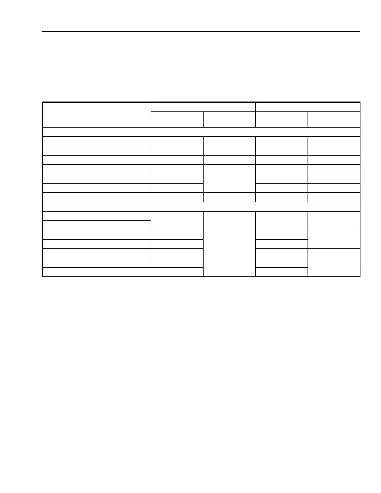
return unless a specific reason exists. Table 1 outlines general
actuator selection. The table indicates actuator positioning desired
on system shutdown and loss of motive force.
Table 1. Valve and Damper Actuator Selection Guide.
Pneumatic Actuators Electric Actuators
Actuator Application
System
Shutdown Loss of Air
System
Shutdown
Loss of
Electricity
Dampers
Outdoor air Closes Closes Closes Closes
Relief air (to outdoor)
Return air Opens Opens Opens Opens
1
VAV fan inlet vanes Closes Closes Closes Closes
VAV box Owner Preference Opens Owner Preference Owner Preference
Multizone hot deck, cold areas Opens Opens Opens
Multizone hot deck, hot areas Closes Closes Closes Closes
Valves
AHU chilled water Closes Opens Closes Stays same
Terminal reheat
Preheat in OA below 1.5ℑC Opens
2
Opens
2
Opens
Preheat in OA above 1.5ℑC Closes Closes
Other hot water Closes
2
Closes
2
Stays same
AHU steam heating Closes Closes
Steam humidifier Closes Closes
1
Return air dampers need no springs if the associated fan is delayed upon start-up to allow the RA damper to properly
position to assure that the fan does not start with both RA and OA dampers closed.
2
If a duct temperature sensor is located near a hot water or steam coil, leaving the coil under control (with a setpoint of
27ℑC to 38ℑC) during equipment shutdown can provide added freeze alarm protection. If variable flow hot water
pumping is provided and a duct low temperature control senses freezing conditions, hot water valves may be
positioned approximately 25% open if a temperature sensor is not available.
 Loading...


