ENGINEERING MANUAL OF AUTOMATIC CONTROL
GENERAL ENGINEERING DATA
474
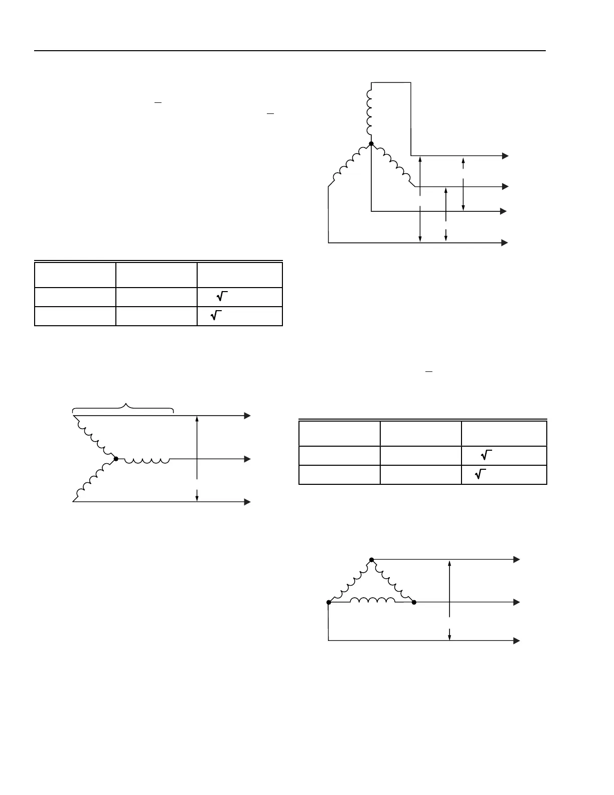
THREE-PHASE THREE-WIRE WYE SYSTEM
The line voltage of a three-phase three-wire wye connected
system (Fig. 4) is equal to √3 times the voltage across the
secondary coils of the transformer. In Figure 4, 277V x √3 =
480V. Notice that in a three-wire wye system the 277V
component is not available for use (see THREE-PHASE FOUR-
WIRE WYE SYSTEM).
The current through the secondary coils of the transformer is
equal to the line current.
This system is most often used for motors and sometimes
for electric resistance heaters.
The power formulas for three-phase three-wire wye con-
nected systems are:
C1811
TRANSFORMER
SECONDARY
277V
10A
277V
10A
277V
10A
E
3
= 480V
E
1
= 480V
I = 10A
I = 10A
I = 10A
E
2
= 480V
LINE 1
LINE 2
LINE 3
Fig. 4. Three-Phase Three-Wire Wye
Connected Transformer.
THREE-PHASE FOUR-WIRE WYE SYSTEM
A three-phase four-wire wye connected system (Fig. 5) adds
a wire connected to the common point of the three transformer
windings. This provides three single-phase voltages between
conductors A, B, or C and N (neutral), that is, the coil voltages
are now available. Conductors A, B, and C provide three-phase
power for heavier loads. The single-phase power is the same
as described in SINGLE-PHASE and the three-phase power
is the same as described in THREE-PHASE THREE-WIRE
WYE SYSTEM.
C1813
120V
120V
120V
E
3
= 120V
E
6
= 208V
E
5
= 208V
E
1
= 120V
A
B
N
C
E
4
= 208V
E
2
= 120V
The total power is the sum of the power in the three coils.
Fig. 5. Three-Phase Four-Wire Wye
Connected Transformer.
THREE-PHASE DELTA SYSTEM
The line voltage of a three-phase delta connected system
(Fig. 6) is equal to the voltage on the secondary coils of the
transformer.
The line current is equal to √3 times the coil current.
The power formulas for three-phase delta connected
systems are:
Phase/Power
Factor
Coil
P=
System
P=
PF = 1 3E
coil
I
coil
3E
line
I
line
PF < 1 3E
coil
I
coil
PF
3E
line
I
line
PF
NOTE: The system power equations assume that the power
and therefore the current on each phase is equal. If
not, the power is calculated for each phase (coil) and
added to get the total power.
Fig. 6. Three-Phase Delta Connected Transformer.
C1812
230
10A
230
10A
230
10A
E
3
= 230
E
1
= 230
E
2
= 230
LINE 2
LINE 1
LINE 3
17.3A
17.3A
17.3A
 Loading...


