ENGINEERING MANUAL OF AUTOMATIC CONTROL
BUILDING AIRFLOW SYSTEM CONTROL APPLICATIONS
278
leveled 10:1 inclined manometer calibrated against a hook
gauge can read to approximately ±1.25 Pa. A standard pitot
tube with an inclined manometer can be used with the following
degree of accuracy:
Table 2. Pitot Tube Accuracy.
It can be seen that the use of the pitot tube in practical
applications is limited at velocities lower than 3 to 4 m/s."
An analysis of the accuracy of the pitot tube at 4 m/s follows:
Velocity Pressure:
VP = (4 ÷ 1.3)
2
= 9.467 Pa
Accuracy:
High
9.467 Pa
+1.250 Pa
10.717 Pa
or 4.26 m/s
Low
9.467 Pa
–1.250 Pa
8.217 Pa
or 3.73 m/s
Range
4.26 m/s
–3.73 m/s
0.53 m/s
or 100.4 ÷ 2=±0.265 m/s
Percent Error:
(±0.265 ÷ 4) x 100 = ±6.6%
In practical situations, the velocity of the air stream is not
uniform across the cross-section of a duct. Friction slows the
air moving close to the walls so the velocity is greater away
from the wall.
To determine the average velocity, a series of velocity pressure
readings at points of equal area is found. It is recommended to
use a formal pattern of sensing points across the duct cross-section.
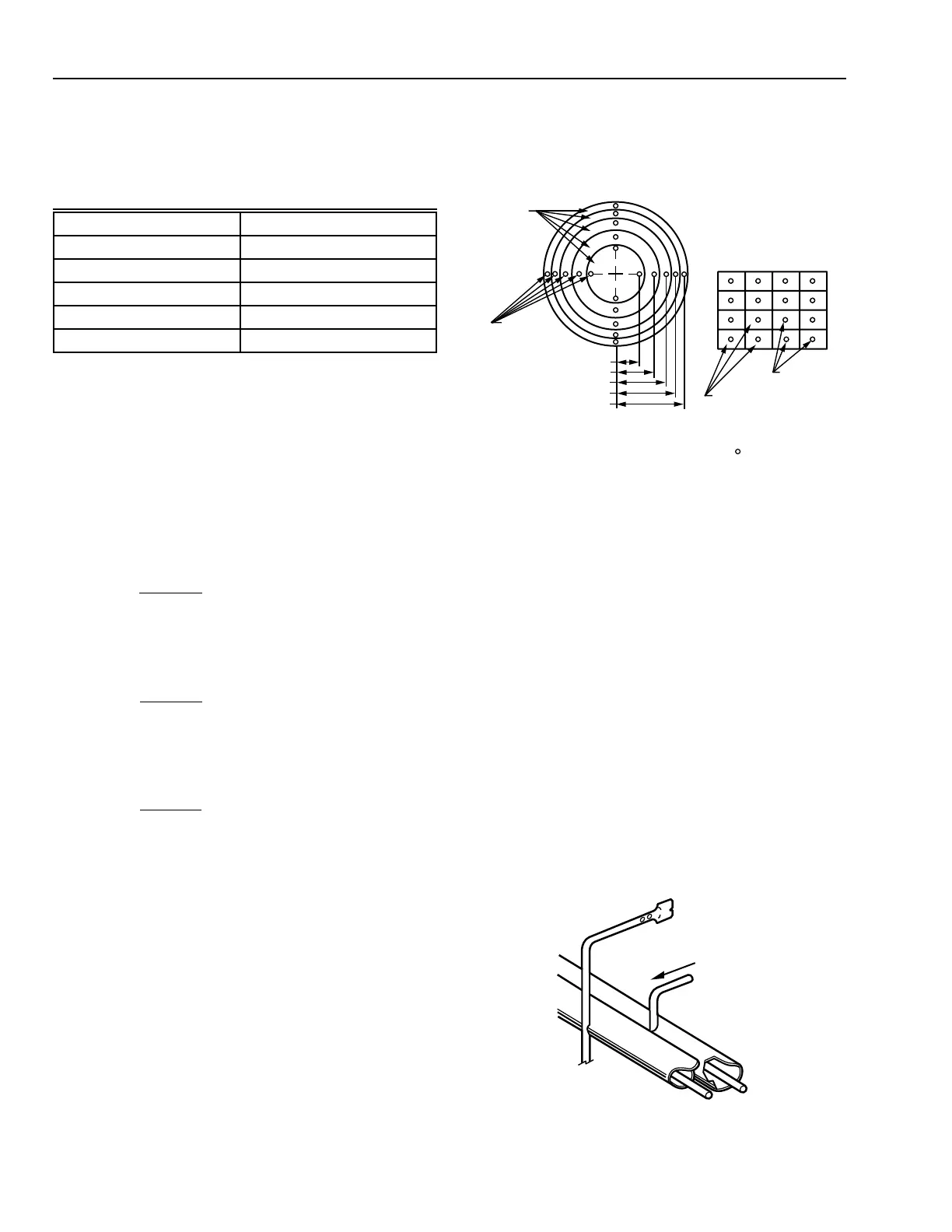
These readings across the duct cross-section are known as traverse
readings. Figure 17 shows recommended pitot tube locations for
traversing round and rectangular ducts. In round ducts, velocity
pressure readings at the centers of the areas of equal concentric
areas are taken. Readings are taken along at least two diameters
perpendicular to each other. In rectangular ducts, readings at the
centers of equal rectangular areas are taken. The velocities are
then mathematically totaled and averaged.
EQUAL
CONCENTRIC
AREAS
CENTERS
OF AREA OF
THE EQUAL
CONCENTRIC
AREAS
0.316 R
0.548 R
0.707 R
0.837 R
0.949 R
ROUND DUCT
16-64 EQUAL
RECTANGULAR AREAS
CENTERS
OF AREAS
RECTANGULAR DUCT
C2657
PITOT TUBE STATIONS INDICATED BY
AIRFLOW
C2658
Fig. 18. Tcheb Tube Sensors and Manifold.
Fig. 17. Pitot Tube Locations for Traversing
Round and Rectangular Ducts.
The principle behind the manual pitot tube transverse is simple
and straightforward. However, care must be taken to obtain
accurate readings without inadvertent violation of the formal
traverse pattern. With the manual pitot tube traverse, individual
velocity readings must be calculated mathematically, totaled, and
divided by the number of readings to obtain average velocity.
TOTAL AND STATIC PRESSURE SENSORS
Other arrangements are available to instantaneously average
sensed pressures and manifold these values to the exterior of
the duct. The Tchebycheff (Tcheb) tube method (Fig. 18) is
one such arrangement. This method separately manifolds the
total and static pressure sensors. Inside each manifold is a tube
with a single slot which receives an average pressure signal
from the manifold. The averaged signals from the total and
static pressure tubes may be used for indication and control
functions. This method assures an accurate reading of flow
conditions and a steady signal.
Velocity (m/s) Percent Error (±)
20 1.04
15 1.60
10 2.94
4 6.6
3 18.6
 Loading...


