ENGINEERING MANUAL OF AUTOMATIC CONTROL
PSYCHROMETRIC CHART FUNDAMENTALS
50
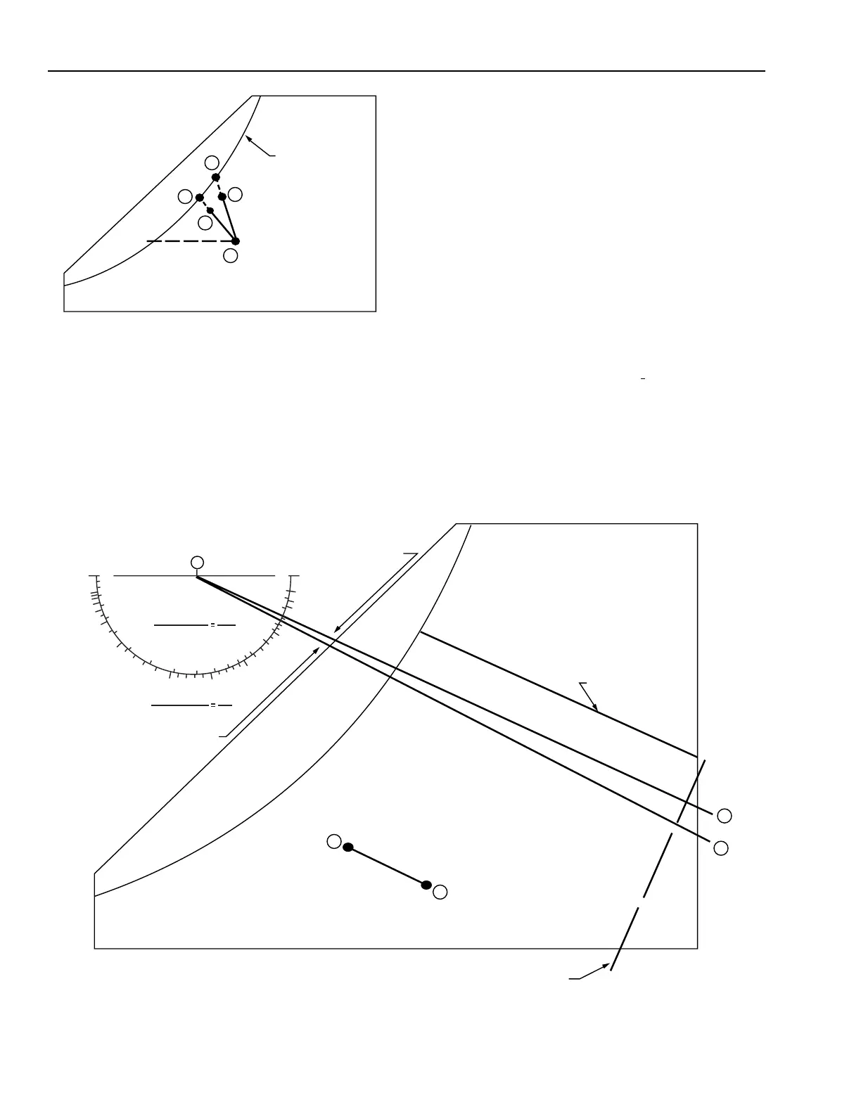
Fig. 23.
Figure 23 illustrates a heated washer where the water
temperature is between the dry-bulb and wet-bulb temperatures
of the air. The air is humidified but also cooled a little. Point B
represents the initial and Point C the final temperature of the
water with reduced humidity demand. Point A represents the
initial and Point E the final temperature of the air. The location
of Points D and E depends on the construction and
characteristics of the washer. The temperature of the water in a
C
B
D
E
A
SATURATION CURVE
C1845
washer is always located on the saturation curve. Note that the
dry-bulb temperature of the air is reduced as it passes through
the washer. This happens because some of its heat is used to
evaporate the water; however, the humidity of the air rises
considerably. In this case, some of the sensible heat of the air
becomes latent heat in the water vapor, but the enthalpy of the
air is increased because of the heat in the water.
VAPORIZING HUMIDIFIER
Vaporizing and water spray humidifiers operate on the principal
of breaking water up into small particulates so they are evaporated
directly into the air. This process is essentially adiabatic since the
enthalpy lines of the water vapor for 0 and 100°C are so close.
The enthalpy of water at 0°C is zero and at 100°C it is 419
kilojoules per kilogram. If air at Point A (Fig. 24) is humidified
by 100°C water, the process follows a line parallel to line C-D
and the 26°C WB line and ends at a point such as Point B. The
actual water temperature of a vaporizing or water spray humidifier
will be between 0°C and 100°C and will usually be around room
temperature so using the zero enthalpy line (C-E) as reference
will not introduce a significant error into the process.
Fig. 24. Psychrometric Chart Showing Line A–B Parallel to Line C–D.
C
0°C WATER = kJ/kg
100°C WATER = 419 kJ/kg
E
D
26°C WB LINE
B
A
CONSTRUCTION LINE, FOR LINE A -B,
PERPENDICULAR TO LINES C-D AND A-B
M15402
TOTAL HEAT
SENSIBLE HEAT
∆ H
s
∆ H
t
∆ h
∆ W
ENTHALPY
HUMIDITY RATIO
1.0 1.0
0
-
∞∞
∞
10.0
5.0
4.0
0.4
0.6
0.8
0.2
3.0
2.5
2.0
1.0
0
-2.0
2.0
4.0
-4.0
-2.0
-1.0
-0.5
-5.0
 Loading...


