ENGINEERING MANUAL OF AUTOMATIC CONTROL
INDIVIDUAL ROOM CONTROL APPLICATIONS
404
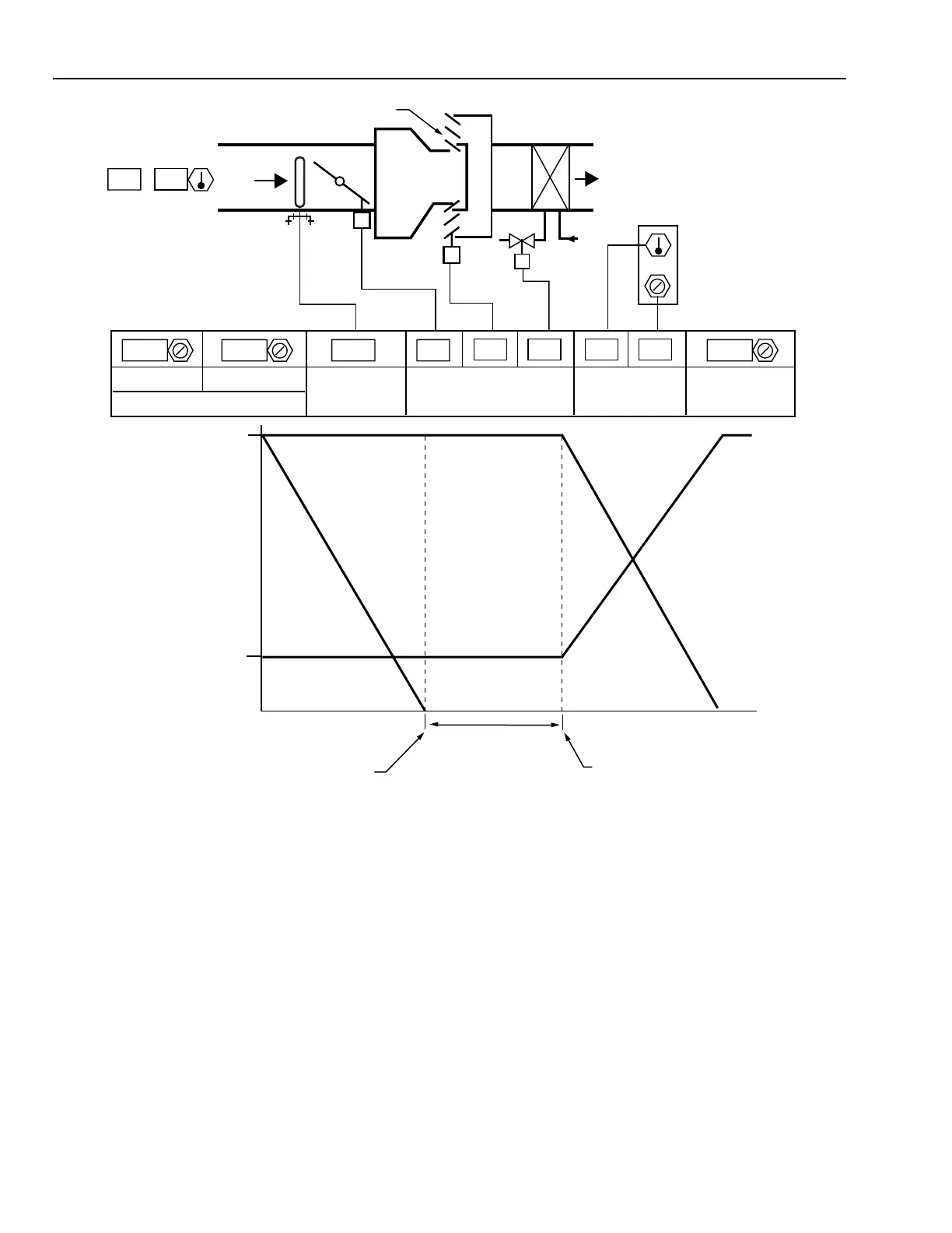
Fig. 7. Induction VAV Air Terminal Unit.
The induction VAV ATU maintains mor e air motion in the
space a t lower loads than a thr ottling VAV ATU. The reheat
coil is optional, and ma y be in the induced air or suppl y air.
Parallel Fan ATU
The par allel fan ATU (Fig. 8) replaces the induction VAV
ATU damper s with a small centr ifugal fan to r ecirculate r etur n
air a t a constant v olume after pr imar y air decr eases. The fan
acts as the f irst sta ge of reheat after pr imar y flow is at minim um
or can be s witched on a t a low primar y flow thr eshold while
pr imar y flow goes to zero. The r eheat coil is optional.
The oper ation cycle in Figur e 8 shows that when space
temper atur e is below the hea ting setpoint, the pr imar y air f low
is at a minim um, and the f an is on. As the hea ting load g oes to
zero, the r eheat valve closes, then the f an stops. After the space
temperature rises through a deadband, as the cooling load
incr eases, the pr imar y air f low increases to maxim um.
Series Fan ATU
The ser ies fan ATU (Fig. 9) delivers a constant v olume of
dischar ge air with a v ar iable volume of AHU suppl y air. In this
ATU, the fan is on contin uously dur ing occupied hour s. Pr imar y
air is modula ted to meet space demand f or cooling . As pr imar y
air damper modula tes closed, more plenum air is dr awn in to
maintain a constant disc har ge volume. Optional r eheat can be
sequenced as required.
0024 24 24
130.35
0.165 0.465 -1.50.575 58
MINIMUM MAXIMUM
kPa
CURRENT
AIRFLOW
(m
3
/s)
PERCENT OPEN
AIRFLOW SETPOINTS (m
3
/s)
HEATING
DEADBAND
COOLING
SETPOINT
TEMPERATURE
WALL MODULE
PLENUM AIR
RHC
VAV BOX
MAX
PRIMARY
AIRFLOW
POSITION
REHEAT
MIN
ZERO
FULL FULL00
DEADBAND
(ADJUSTABLE)
M15308
HEATING
LOAD
HEATING SETPOINT
COOLING SETPOINT
COOLING
LOAD
PRIMARY
DAMPER AIRFLOW
INDUCTION
DAMPER
POSITION
OPEN
CLOSED
INDUCTION
DAMPER
PRIMARY
AIR
 Loading...


