ENGINEERING MANUAL OF AUTOMATIC CONTROL
INDIVIDUAL ROOM CONTROL APPLICATIONS
418
Thr ee room temper atur e setpoints ar e shown, free cooling, a
heating deadband , and a mec hanical cooling deadband . The fr ee
cooling setpoint ma y be man ual on the w all module , or softw ar e
(with softw ar e bounds). All unit v entilator s are switched to the
free cooling economiz er mode of oper ation globall y anytime the
OA is suita ble (see the Air Handling System Contr ol Applica tions
section). When the O A is unsuita ble for fr ee cooling assistance ,
and c hilled water is a vailable, the OA damper is r etur ned to the
minim um ventila tion.
PRECAUTIONS AND CONDITIONS FOR
SUCCESSFUL OPERATION
Unit ventilator s requir e protection fr om blocked airf low,
power failur e, and coil fr eeze-up.
Blocked Airflow
Pr oper airf low is essential to sa tisfying space temper atur e
and v entila tion r equir ements. Objects loca ted dir ectly over the
dischar ge air v ents can inhibit or b lock airf low. Cleaning or
replacing the f ilter as needed and c leaning dust and dir t fr om
unit v entila tor coils impr oves airf low thr ough the unit v entila tor.
Power Failure
Pr ecautions f or po wer and air f ailur e must be specif ied when
the automatic control system is designed. Pneumatic systems
requir e an electr ic-pneuma tic switch to exhaust the v alve and
damper actua tor dia phr agms on a po wer or air f ailur e. The outdoor
air damper c loses and the r etur n air damper and coil v alve open.
Electr ic, electr onic, and dig ital contr ol systems should be specif ied
with spring-return actuators that close the outdoor air damper and
open the r etur n air damper on po wer failur e.
Coil Freeze-Up
Causes of coil freeze-up include central system circulating
pump or boiler f ailur e, outdoor air damper or contr ol valve
malfunction, and une ven temper atur e distr ibution. A low-limit
contr oller can help pr event coil fr eeze-up b y overriding other
control system components to close the outdoor air damper
and open the r etur n air damper and coil v alve. Effective freeze-
up pr otection de pends on a vailable heat in the system and f low
through the coils.
Coils can also fr eeze when low-temper atur e outdoor air leaks
thr ough def ective damper s. Frequent inspection of damper s
should be made to detect bent and br oken damper linka ges,
war ped damper b lades, and def ective or missing b lade seals
tha t can contr ibute to coil fr eeze-up.
Low temper atur e switches to stop the f an and c lose the OA
damper should be pr ovided wher e freezing OA conditions ar e
likely. With dig ital systems, dur ing unoccupied per iods, the low
temper atur e switch ma y star t the f an and the r ecircula ting pump.
FAN COIL UNITS
GENERAL
Fan coil units ar e similar to unit v entila tor s except tha t fan
coil units do not ha ve damper s and typicall y do not ha ve an
outdoor air intak e. They may also be conf igured for installa tion
above a ceiling with ceiling or w all mounted disc har ge and
retur n air g rills. Fan coil units pr ovide hea ting and/or cooling
for single-z one ar eas such as a par tments, offices, and indi vidual
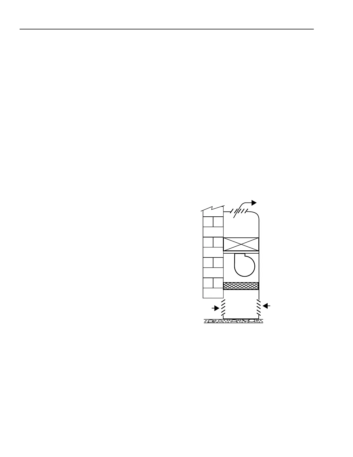
hotel or hospital r ooms. Figure 30 shows a typical f an coil unit
compr ising a finned-tube coil, a fan section, and a f ilter. The
fan cir culates air fr om the space acr oss the coil. The coil ma y
use steam or hot w ater fr om a centr al system or electr ic
resistance elements to satisfy heating requirements. Chilled
water or DX coils can be used f or cooling . Units used f or cooling
only or for both hea ting and cooling ha ve a built-in condensa te
dr ain pan to collect and dr ain condensa te on the cooling c ycle.
Fig. 30. Fan Coil Unit.
Fan coil units ar e classified as two-pipe hea ting, two-pipe
cooling, two-pipe hea ting/cooling , or four-pipe hea ting/cooling .
Contr ol for a f an coil unit typicall y compr ises a r oom or r etur n
air ther mosta t for indi vidual r oom contr ol. The ther mostat
regulates a valve while a fan moves air thr ough the unit and
across the coil. The fan r uns contin uously, is scheduled , or is
cycled on and of f by the ther mosta t. The fan is often thr ee speed
with a local three-speed switch. Some applications control only
the fan oper ation and allo w the conditioning medium to f low
continuously in the coil. F an coil units can use pneuma tic,
electric, electronic, or digital control.
C3038
DISCHARGE
AIR
WALL
OUTDOOR
AIR
(OPTIONAL)
RETURN
AIR
FILTER
COIL
FAN
 Loading...


