PNEUMATIC CONTROL FUNDAMENTALS
ENGINEERING MANUAL OF AUTOMATIC CONTROL
61
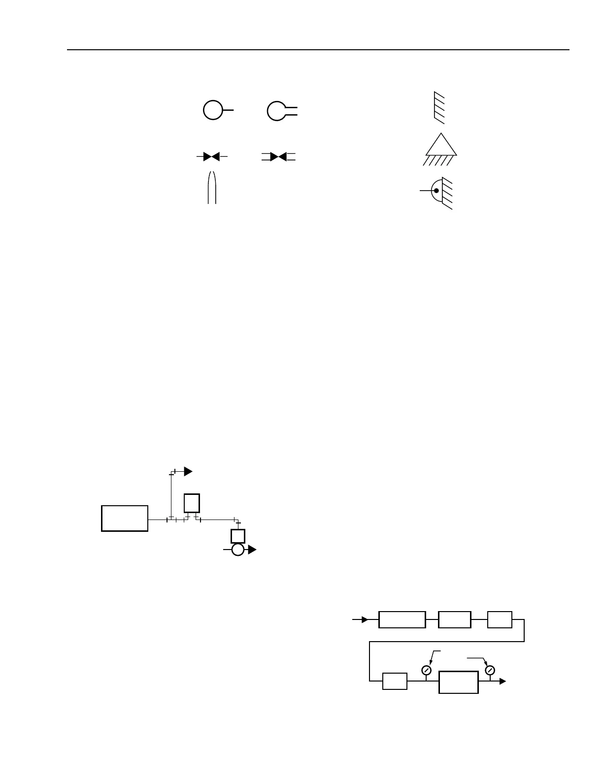
SYMBOLS
M
M
OR
OR
MAIN AIR SUPPLY
RESTRICTOR
NOZZLE
FIXED POINT
FULCRUM
PIVOT POINT
C1082
BASIC PNEUMATIC CONTROL SYSTEM
GENERAL
A pneumatic control system is made up of the following
elements:
— Compressed air supply system
— Main line distribution system
— Branch lines
— Sensors
— Controllers
— Actuators
— Final control elements (e.g., valves, dampers)
A basic pneumatic control system consists of an air supply, a
controller such as a thermostat, and an actuator positioning a
valve or damper (Fig. 1).
In a typical control system, the final control element (a valve
or a damper) is selected first because it must produce the desired
control results. For example, a system designed to control the
flow of water through a coil requires a control valve. The type
of valve, however, depends on whether the water is intended
for heating or cooling, the water pressure, and the control and
flow characteristics required. An actuator is then selected to
operate the final control element. A controller and relays
complete the system. When all control systems for a building
are designed, the air supply system can be sized and designed.
AIR SUPPLY AND OPERATION
The main line air supply is provided by an electrically driven
compressor pumping air into a storage tank at high pressure
(Fig. 2). A pressure switch turns the compressor on and off to
maintain the storage tank pressure between fixed limits. The
tank stores the air until it is needed by control equipment. The
air dryer removes moisture from the air, and the filter removes
oil and other impurities. The pressure reducing valve (PRV)
typically reduces the pressure to 125 to 150 kPa. For two-
pressure (day/night) systems and for systems designed to change
from direct to reverse acting (heating/cooling), the PRV switches
between two pressures, such as 90 and 125 kPa. The maximum
safe air pressure for most pneumatic controls is 170 kPa.
C2353
COMPRESSED
AIR SUPPLY
SYSTEM
MAIN BRANCH
ACTUATOR
VALVE
THERMOSTAT
TO OTHER
CONTROLLERS
M
B
Fig. 1. Basic Pneumatic Control System.
The controller receives air from the main line and regulates its
output pressure (branchline pressure) as a function of the
temperature, pressure, humidity, or other variable. The branchline
pressure from the controller can vary from atmospheric to full
mainline pressure. The regulated branchline pressure energizes
the actuator, which then assumes a position proportional to the
branchline pressure applied. The actuator usually goes through
its full stroke as the branchline pressure changes from 20 kPa to
90 kPa. Other pressure ranges are available.
AIR
SUPPLY
IN
AIR
COMPRESSOR
STORAGE
TANK
AIR
DRYER
FILTER
PRESSURE
GAGES
PRESSURE
REDUCING
VALVE
MAIN AIR TO
PNEUMATIC
CONTROL
SYSTEM
C2616-1
Fig. 2. Compressed Air Supply System.
 Loading...


