ENGINEERING MANUAL OF AUTOMATIC CONTROL
VALVE SELECTION AND SIZING
437
The close-off pressure in a diverting valve equals the
maximum value of the inlet pressure minus the minimum value
of the downstream pressure.
Globe diverting valves must not be used for mixing service.
As with mixing valves used for diverting service, media pressure
drop across the valve can cause it to slam shut with resulting
loss of control.
EXAMPLE:
A diverting valve application has 140 kPa maximum on
the inlet port, one outlet port discharging to the
atmosphere, and the other outlet port connecting to a tank
under 70 kPa constant pressure. The pressure difference
between the inlet and the first outlet port is 140 kPa and
between the inlet and second outlet port is 70 kPa. The
application requires a diverting valve with at least 140 kPa
close-off rating.
VALVE SIZING
Every valve has a capacity index or flow coefficient (K
v
).
Typically determined for the globe and ball valves at full open
and about 60 degrees open for butterfly valves. K
v
is the quantity
of water in cubic meters per hour between 5 and 40°C that
flows through a valve with a pressure differential of 10
5
pascals.
Sizing a valve requires knowing the medium (liquid or gas)
and the required pressure differential to calculate the required
K
v
. When the required K
v
is not available in a standard valve,
select the next closest and calculate the resulting valve pressure
differential at the required flow to verify to verify acceptable
performance.
After determination of the valve K
v
, calculation of the flow
of any medium through that valve can be found if the
characteristics of the medium and the pressure drop across the
valve are known.
WATER VALVES
Determine the capacity index (Kv) for a valve used in a water
application, using the formula:
Determining the K
v
of a water valve requires knowing the
quantity of water (m
3
/h) through the valve and the pressure
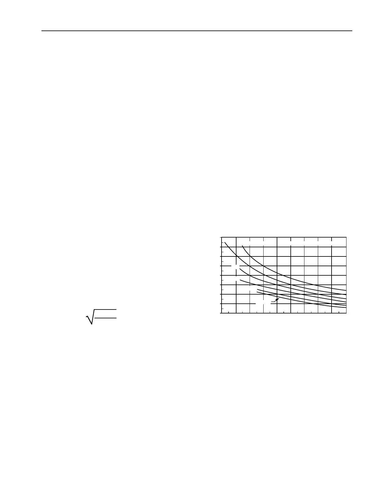
drop (∆P) across the valve. If the fluid is a glycol solution, use
the pressure drop multipliers from either Figure 14 or 15. See
the sections on QUANTITY OF WATER and WATER VALVE
PRESSURE DROP. Then select the appropriate valve based
on K
v
, temperature range, action, body ratings, etc., per VALVE
SELECTION guidelines.
REPRINTED BY PERMISSION FROM ASHRAE HANDBOOK—
1996 HVAC SYSTEMS AND EQUIPMENT
K
v
=Q
ρ
∆P • 10
Where:
Q = Flow of fluid in cubic meters per hour
required to pass through the valve.
ρ = Specific gravity of the fluid (water =
1000 kg/m
3
).
∆P = Pressure drop in kPa. See Figures 14 and 15
for glycol solution correction values.
Fig. 14. Pressure Drop Correction for
Ethylene Glycol Solutions.
-20 -10 0 10 20 30 40 50 60 70
PRESSURE DROP CORRECTION FACTOR
TEMPERATURE, °C
M15319
40%
10%
20%
30%
WATER
50% BY MASS
0.8
0.9
1.1
1.3
1.5
1.0
1.2
1.4
1.6
ETHYLENE GLYCOL SOLUTION
 Loading...


