ENGINEERING MANUAL OF AUTOMATIC CONTROL
DAMPER SELECTION AND SIZING
462
DAMPER PRESSURE DROP
If the duct size, damper size, and the airflow are known, use
the method in Table 6 to determine the actual pressure drop
across the damper:
For example, for a 1.50 m
2
parallel blade
damper in a 1.69 m
2
duct with an airflow of 9.45 m
3
/s, determine the pressure drop
across the damper as shown in Table 7.
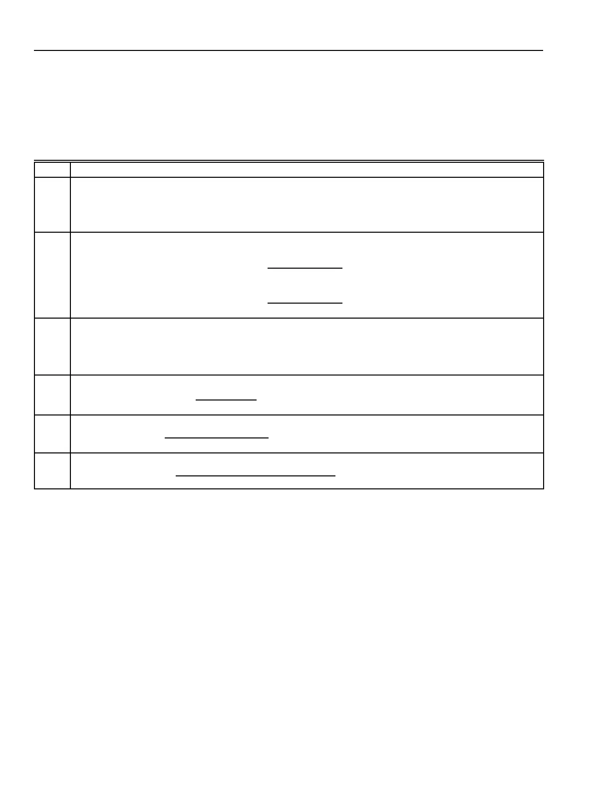
Table 6. Damper Pressure Drop Calculation Procedures
Step Procedure
1 a. Determine the number of sections required.
The area of the damper must not exceed the maximum size for a single section. If the damper area exceeds the
single section area:
b. Divide the area of the damper, the area of the duct, and the airflow by the number of damper sections.
c. Use the values from Step b in the following Steps.
2
Calculate the free area ratio
a
:
For parallel blade dampers, the free area ratio is found:
Ratio = (0.0798 x damper area m
2
)
0.1007
x
Damper area (m
2
)
Duct area (m
2
)
For opposed blade dampers, the free area ratio is found:
Ratio = (0.0180 x damper area m
2
)
0.0849
x
Damper area (m
2
)
Duct area (m
2
)
3 Using the ratio from Step 1, calculate the pressure drop at 5.08 m/s.
For ratios ≤ 0.5:
Pressure drop (Pa) = –11.64 x (1 – ratio
–2.562
)
For ratios > 0.5:
Pressure drop (Pa) = –3.114 x (1 – ratio
–4.274
)
4 Calculate the approach velocity:
Approach velocity (m
3
/s) =
Airflow (m
3
/s)
Duct Area (m
2
)
5 Using the approach velocity from Step 3, calculate a correction factor:
Correction factor =
25.8
[Approach velocity (m/s)]
2
6 Calculate the pressure drop across the damper:
Pressure drop (Pa) =
Pressure drop (Pa) at 5.08 m/s (Step 2)
Correction factor (Step 4)
a
The free area of a damper is the open portion of the damper through which air flows. The free area ratio is the open area in
a damper divided by the total duct area.
 Loading...


