ENGINEERING MANUAL OF AUTOMATIC CONTROL
AIR HANDLING SYSTEM CONTROL APPLICATIONS
244
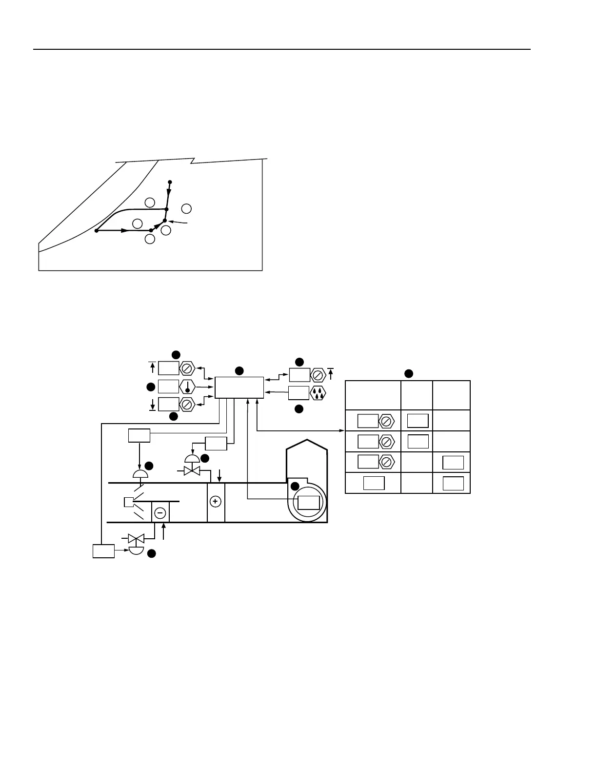
WATER COIL FACE AND BYPASS SYSTEM CONTROL
Functional Description
The following results are obtained:
Item
No. Explanation
1 Mixed air temperature at cooling design
condition.
2 Air entering the cooling coil is cooled along a
line of constant moisture content until saturation
is approached. Near saturation the moisture con-
tent is reduced as the air is cooled. This process
involves both latent and sensible cooling.
3 The final leaving air temperature necessary to
satisfy space requirements will be maintained
by reheating along a constant moisture line.
4 Heating coil discharge.
5 This process line represents the increase in
temperature and humidity that occurs due to
the sensible and latent heat gains in the space.
Item
No. Function
1 Control system energizes when fan is turned
on (See FAN SYSTEM START-STOP
CONTROL).
2-4 Space temperature PI control loops have heat
and cool setpoints with deadband.
5,6 Space humidity sensor and setpoint enable
dehumidification.
7-9 Heating and cooling valves and face and
bypass dampers position for heating, cooling,
and dehumidifying cycles.
10 Stages chilled water and face-and-bypass
damper loading.
11 Control program coordinates cooling, heating,
dehumidifying, and fan and hot water
interlock control.
In the following chart it is assumed that:
1. Desired space condition is 24°C DB and a maximum of
50% RH.
2. OA condition is 27°C DB and 26°C WB.
3. Air entering the system is from the ECONOMIZER
CYCLE DECISION application. The system operates on
25 percent OA during the cooling cycle.
4. Cooling coil leaving air temperature is 13°C.
M15174
SA
11
6
5
2
70
90
32
SUPPLY
FAN
COOL
HEAT
ON
1
CONTROL
PROGRAM
3
4
7
9
25
50
50
22
23.5
MA
8
10
0
60
10
100
COOL OR
DEHUMIDIFIER
DEMAND
CHW
VALVE
0
100
0
100
FACE
DAMPER
C3253
RA 24°C DB,
50% RH
MA
OA 27°C DB,
26°C WB
1
2
3
5
4
COOLING COIL
DISCHARGE
13°C DB
 Loading...


