ENGINEERING MANUAL OF AUTOMATIC CONTROL
PNEUMATIC CONTROL FUNDAMENTALS
86
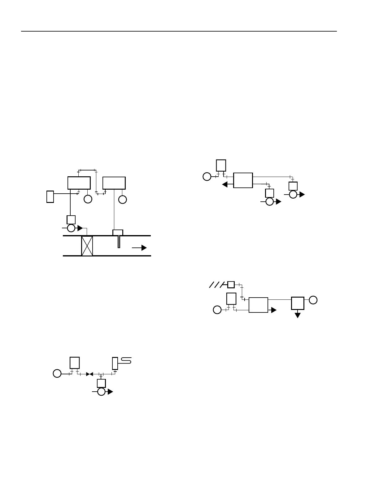
Low-limit control applications typically use a direct-acting
primary controller and a normally open control valve. The
direct-acting, low-limit controller can lower the branchline
pressure regardless of the demands of the room controller, thus
opening the valve to prevent the discharge air temperature from
dropping below the limit controller setpoint. Whenever the low-
limit discharge air sensor takes control, however, the return air
sensor will not control. When the low-limit discharge air sensor
takes control, the space temperature increases and the return
air sensor will be unable to control it.
A similar combination can be used for a high-limit heating
control system without the selector relay in Figure 61. The limit
controller output is piped into the exhaust port of the primary
controller, which allows the limit controller to limit the bleed-
down of the primary controller branch line.
C2381
B S M
DISCHARGE
AIR
LIMIT
SENSOR
B S M
M
PRIMARY
CONTROLLER (DA)
LOW-LIMIT
CONTROLLER (DA)
N.O.
VALVE
HEATING COIL
M
B S M
PRIMARY
SENSOR
Fig. 61. High-Limit Control (Heating Application).
Bleed-type, low-limit controllers can be used with pilot-
bleed thermostats (Fig. 62). A restrictor installed between the
thermostat and the low-limit controller, allows the low limit
controller to bleed the branch line and open the valve. The
restrictor allows the limit controller to bleed air from the valve
actuator faster than the thermostat can supply it, thus
overriding the thermostat.
M
M B
DA
THERMOSTAT
N.O. VALVE
C2350
DA
LOW-LIMIT
CONTROLLER
MANUAL SWITCH CONTROL
Common applications for a diverting switch include on/off/
automatic control for a heating or a cooling valve, open/closed
control for a damper, and changeover control for a two-pressure
air supply system. Typical applications for a proportional
switch include manual positioning, remote control point
adjustment, and minimum damper positioning.
Figure 63 shows an application for the two-position manual
switch. In Position 1, the switch places the thermostat in
control of Valve 1 and opens Valve 2 by bleeding Valve 2 to
zero through Port 1. When turned to Position 2, the switch places
the thermostat in control of Valve 2 and Valve 1 opens.
M
M
B
THERMOSTAT
C2351
3
1
4
2
EXH
TWO-POSITION
SWITCH
N.O. VALVE 1
N.O. VALVE 2
NOTE:
POSITION 1: PORTS 3 AND 2, 1 AND 4 CONNECTED
POSITION 2: PORTS 3 AND 4, 1 AND 2 CONNECTED
M
M
B
DA
THERMOSTAT
C2352
THREE-POSITION
SWITCH
NOTE: POSITION 1: AUTO—PORTS 2 AND 4 CONNECTED
POSITION 2: CLOSED—PORTS 2 AND 3 CONNECTED
POSITION 3: MANUAL—PORTS 2 AND 1 CONNECTED
DAMPER
ACTUATOR
M
2
4
1
3
EXH
B
E
M
EXH
MANUAL
POSITIONING
SWITCH
Fig. 62. Bleed-Type, Low-Limit Control System.
Fig. 63. Application for Two-Position Manual Switch.
Figure 64 shows an application of the three-position switch
and a proportioning manual positioning switch.
Fig. 64. Application for Three-Position Switch
and Manual Positioning Switch.
In Position 1, the three-position switch places the thermostat
in control of the damper. Position 2 closes the damper by
bleeding air pressure to zero through Port 3. Position 3 allows
the manual positioning switch to control the damper.
 Loading...


