ENGINEERING MANUAL OF AUTOMATIC CONTROL
BUILDING AIRFLOW SYSTEM CONTROL APPLICATIONS
273
Fan power is the actual fan power required to drive the fan.
Po = Theoretical Po ÷ Fan efficiency
=(m
3
/s x FTP) ÷ Fan efficiency
The fan power is always larger than the theoretical fan power
due to inefficiencies. The actual power of the fan can be
determined only by testing.
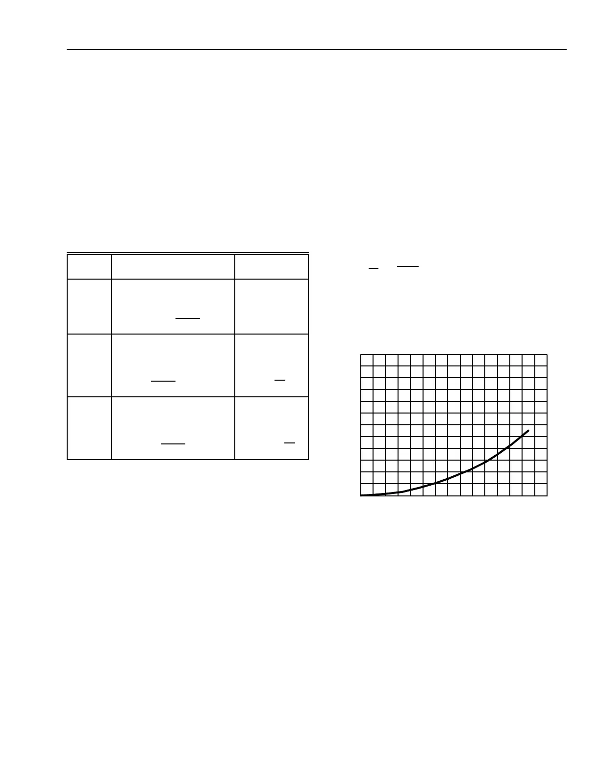
DUCT SYSTEM CURVES
Fan unit duct systems have a certain amount of friction, or
resistance, to the flow of air. Once this resistance of the duct
system is known for a specific volume of airflow, a curve can
be drawn based on the relationship:
This formula is merely another way of stating that pressure
(P) changes as the square of the airflow (m
3
/s).
The system curve (also called system resistance, duct
resistance, or system characteristic) is similar to Figure 6.
FAN LAWS
Fan laws (Table 1) are simple and useful when dealing with
changing conditions. Three important laws deal with speed
changes:
1. Airflow varies directly with the fan speed. For example,
doubling the fan speed (rpm) doubles the airflow (m
3
/s)
delivery.
2. Static pressure varies as the square of the fan speed. For
example, doubling the fan speed (rpm) develops four
times the static pressure (Pa).
3. Power varies as the cube of the fan speed. For example,
doubling the fan speed (rpm) requires eight times the fan
power (Po).
Table 1. Fan Laws
FAN POWER
The theoretical fan power (Po) required to drive a fan is the
fan power required if there were no losses in the fan (100 percent
efficiency). The fan power formula is:
Theoretical Po = (m
3
/s x FTP)
Where:
m
3
/s = Quantity of air
Po = Power in watts (W)
FTP = Fan total pressure.
Fig. 6. System Curve.
FAN CURVE AND SYSTEM CURVE COMPARISON
In order to deliver the required air quantity, a fan must be
selected that can overcome the duct resistance. However,
because of dampers repositioning and other equipment changes,
resistance of the duct may change. The results of such conditions
can be seen in Figure 7.
STATIC PRESSURE (∆P) Pa
600
550
500
450
400
350
300
250
200
150
100
50
0
5.0 10.0 15.00
C4074
AIRFLOW m
3
/s
Variable When Speed Changes
When Density
Changes
Varies DIRECT with Speed
Ratio
Does Not
Change
Airflow
m
3
/s
2
= m
3
/s
1
()
RPM
2
RPM
1
2
Varies with SQUARE of
Speed Ratio
Varies DIRECT
with Density
Ratio
Pressure
P
2
= P
1
()
RPM
2
RPM
1
2
P
2
= P
1
()
D
2
D
1
Varies with CUBE of Speed
Ratio
Varies DIRECT
with Density
Ratio
Power
Po
2
= Po
1
()
RPM
2
RPM
1
3
Po
2
= Po
1
()
D
2
D
1
P
2
P
1
=
()
m
3
/s
2
m
3
/s
1
2
 Loading...


