ENGINEERING MANUAL OF AUTOMATIC CONTROL
INDIVIDUAL ROOM CONTROL APPLICATIONS
420
Digital Contr ol of the tw o pipe hea ting/cooling f an coil unit
should a bove could be as F igure 33. The fans could be ba tch
scheduled via one or mor e optimum star t pr ograms. Wall
modules could ha ve a cooling setpoint knob (with softw are
bounds) and a hea ting deadband . The enter ing water
temperature (from a plant sensor) and the outside air temperature
ar e shown for oper ator inf ormation. The hea ting/cooling plant
could be controlled similarly to that described in the paragraph
Hot Water Plant Consider ations.
The four-pipe heating/cooling fan coil unit control would
be identical except the valves would be sequenced through the
deadband.
FOUR-PIPE HEATING/COOLING, SPLIT COIL
Year-round hea ting and cooling is possib le at each unit with a
four-pipe hea ting/cooling , split coil a pplica tion (F ig. 34). A fan
coil unit in one zone can cool while a unit in another zone heats.
The control system comprises a room thermostat connected to
two valves, one contr olling hot w ater f low and the other contr olling
chilled water f low. Valves can be tw o-way or thr ee-way.
When space temper atur e is below the ther mosta t setpoint,
the hot w ater suppl y valve modula tes open and hot w ater f lows
thr ough the hea ting coil. As space temper atur e increases, the
hot water v alve modula tes closed. As space temper atur e rises
above setpoint, the ther mosta t signal star ts to open the c hilled
water v alve. The r oom ther mosta t thr ottling r ange and v alve
actua tor mo vement should be selected to pr ovide a “deadband”
between hea ting and cooling so tha t both v alves ar e closed when
space temper atur e is satisfied. The fan can be oper ated b y a
local fan switch or a centr al time c lock.
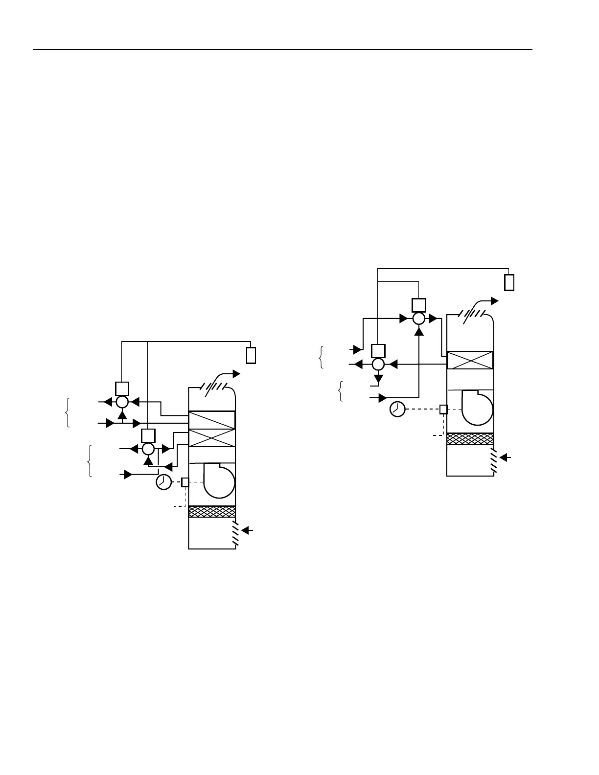
FOUR-PIPE HEATING/COOLING, SINGLE COIL
Figur e 35 shows the single-coil method f or four-pipe hea ting/
cooling. A ther mosta t contr ols two thr ee-way valves to r egulate
the flow of chilled or hot w ater into a single coil.
Fig. 34. Four-Pipe Heating/Cooling Fan
Coil Unit with a Split Coil.
C3030-1
DISCHARGE
AIR
THERMOSTAT
RETURN
AIR
COOLING
COIL
FILTER
HEATING
COIL
FAN
POWER
TIME
CLOCK
3-WAY MIXING
VALVE
3-WAY
MIXING
VALVE
SUPPLY
SUPPLY
RETURN
RETURN
HOT
WATER
CHILLED
WATER
Fig. 35. Four-Pipe Heating/Cooling Fan Coil Unit.
This system r equir es special thr ee-way sequencing v alves tha t
shut of f all flow at the mid dle of the ther mosta t thr ottling r ange.
On a f all in space temper atur e, with the c hilled water suppl y and
retur n por ts close, the hot w ater r etur n por t opens 100 per cent,
and the suppl y valve hot w ater por t modula tes the hot w ater f low
to maintain space temper atur e. As space temper atur e rises, the
hot water suppl y and r etur n por ts close and f low thr ough the coil
is stopped . When space temper atur e rises above the ther mosta t
setpoint, the chilled water r etur n por t opens to 100 per cent flow
and the suppl y por t modula tes chilled w ater f low thr ough the coil
to maintain the space temper atur e. Both the c hilled water and hot
water suppl y por ts ar e closed in a deadband betw een hea ting and
cooling oper ations. The contr ol is similar to ha ving sequenced
modula ting tw o-way valves on the HW and CW supplies and
sequenced tw o-position tw o-way valves on the r etur ns. The fan
can be oper ated b y a local f an switch or a centr al time c lock.
C3031
DISCHARGE
AIR
THERMOSTAT
RETURN
AIR
FILTER
HEATING/
COOLING
COIL
FAN
POWER
FAN
SWITCH
TIME
CLOCK
3-WAY
DIVERTING
VALVE
3-WAY
MIXING
VALVE
SUPPLY
SUPPLY
RETURN
RETURN
HOT
WATER
CHILLED
WATER
 Loading...


