ENGINEERING MANUAL OF AUTOMATIC CONTROL
INDIVIDUAL ROOM CONTROL APPLICATIONS
400
SINGLE-DUCT VAV ATU
System Configuration
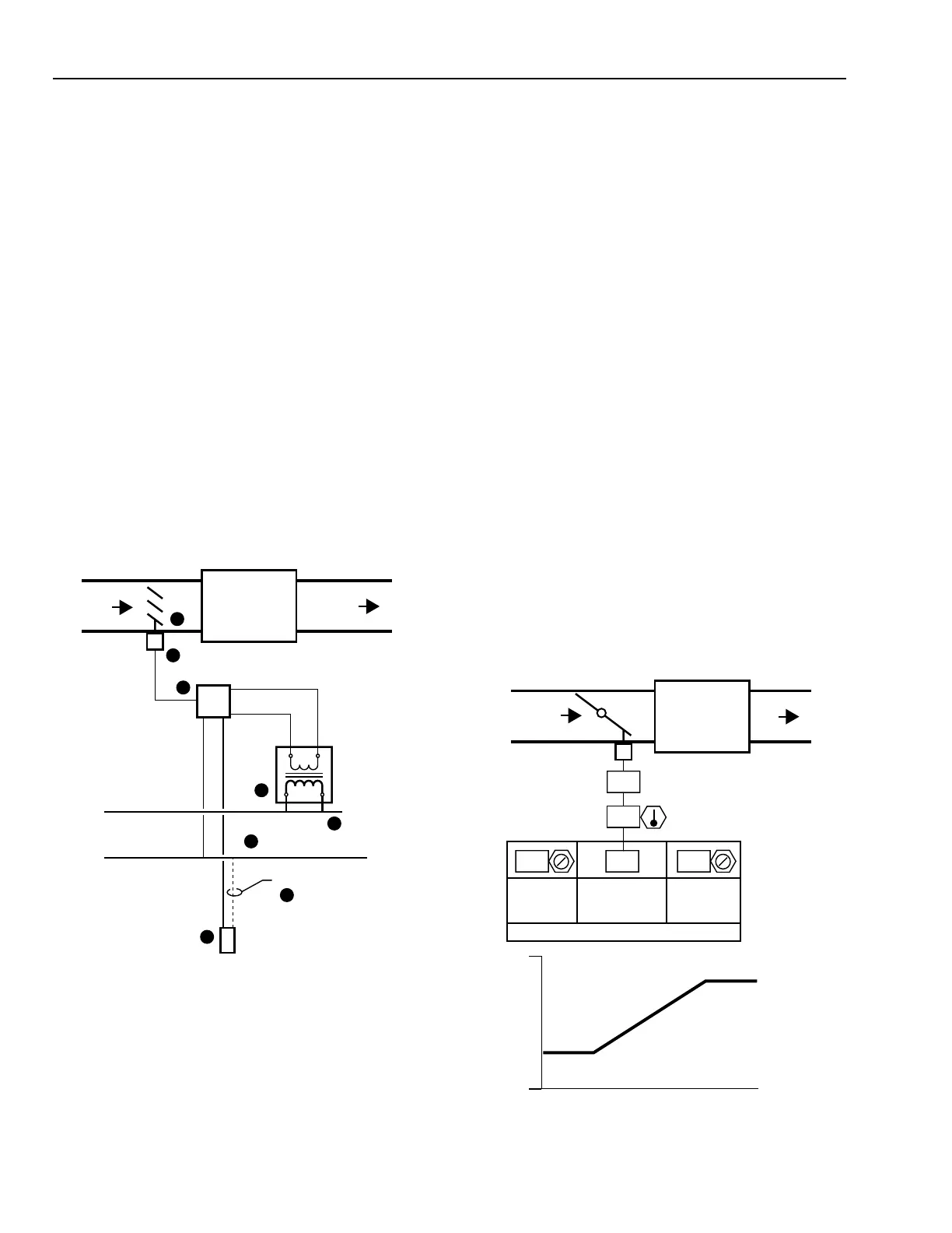
Figur e 2 is a schema tic of the equipment sho wn in the contr ol
diagram Thr ottling VAV ATU in F igure 3. The elements ar e:
1. Flow contr ol damper .
2. Damper actua tor, usuall y electr ic, bidir ectional.
3. A digital contr oller.
4. A low voltage contr ol tr ansformer.
5. A line voltage power sour ce.
6. A digital comm unica tions bus for contr ol and BMS
functions.
7. An optional b us connection to the space w all module f or
easy access from a portable control terminal
8. A wall module .
In this pressure dependent application, the damper has
minim um and maxim um softw ar e contr ol positions. In other
applica tions, the contr oller can ha ve connections to the air f low
rings, reheat valve or electr ic heat contactor s, occupanc y sensor
input, and f an r elays.
The wall module contains an y combina tion of temper atur e
sensor, setpoint adjustment knob , after hour o verride push
button, occupanc y status LED , or an LCD displa y and k eypad .
Fig. 2. Single-Duct VAV ATU
In a single-duct VAV ATU, a temper atur e contr oller connected
to a damper actua tor contr ols the volume of cool air deli vered
to the space . A reheat coil may be ad ded, in which case the
contr oller sequences the oper ation of the damper and the v alve
or contactor . On a f all in space cooling load , the damper g oes
to minim um position bef ore any heat is pr ovided. A single-
duct VAV system ma y also have a separ ate per imeter hea ting
system suc h as a f inned-tube r adia tor or f an coil units to sa tisfy
heating requirements.
DAMPER
PRIMARY
AIR
SUPPLY
AIR
DAMPER
ACTUATOR
DIGITAL
CONTROLLER
DC
24 VOLT
POWER
TRANSFORMER
LINE VOLTAGE
POWER
DIGITAL
COMMUNICATIONS BUS
OPTIONAL
ROOM SENSOR/
WALL MODULE
3
2
1
4
5
6
7
8
T
M10520
Throttling VAV ATU
The throttling VAV ATU (Fig. 3) is the simplest and least
expensive ATU. A room controller controls the operation of
the damper actuator using PI control. The throttling VAV ATU
usually has software minimum and/or maximum damper
position limits for limiting air volume. Because the unit is
pressure dependent, volume at any given damper position varies
with the inlet duct static pressure. Maintaining a stable duct
static pressure at the end of the duct run is important for proper
operation. Proper setting of the minimum-flow limit is essential
for adequate circulation and is properly set with all boxes
operating at their minimum damper positions. At this operating
point, the duct static pressure near the fan will be lower than
at full load. If the minimum damper positions are each set
with other boxes at their maximum damper positions, when
the load decreases and the pressure drops near the fan,
inadequate circulation results at boxes near the fan.
Compromises in minimum and maximum airflow control on
pressure dependent systems result if the loads vary. Care must
be exercised in set-up and balancing to assure that all zones
get no less than minimum air flow at all loadings and that all
zones demanding maximum air flow get no less than maximum
air flow at all loadings.
The space temperature setpoint is the value set by the
occupant on the w all module . With this option, the BMS
oper ator ma y assign software limits to the set v alue. Values
may be set outside the limits b ut the contr ol program ignor es
them and oper ates at the limits set in softw ar e. Another option
frequentl y used in open and pub lic spaces is to ha ve no setpoint
knob on the module and to ha ve a single software setpoint
displayable and commandable from the BMS.
Fig. 3. Throttling VAV Air Terminal Unit.
M15304
24
74
24 24 77
MINIMUM
DAMPER
POSITION
MAXIMUM
DAMPER
POSITION
CURRENT
TEMPERATURE
SPACE
TEMPERATURE
KNOB
SETPOINT SCHEDULE
OPEN
DAMPER
POSITION
CLOSED
MINIMUM
POSITION
MAXIMUM
POSITION
LOW
HIGH
SPACE COOLING LOAD
PERCENT
OPEN
PRIMARY
AIR
 Loading...


