ELECTRONIC CONTROL FUNDAMENTALS
ENGINEERING MANUAL OF AUTOMATIC CONTROL
125
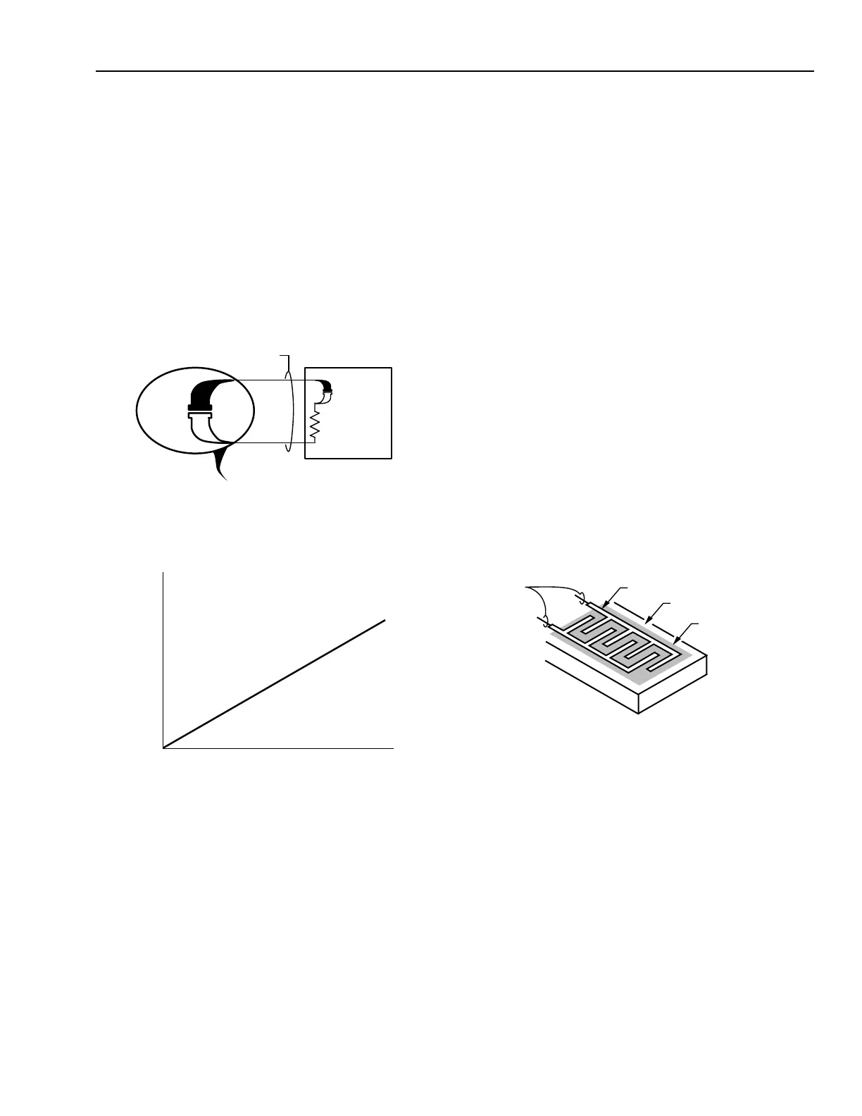
Thermocouples
A thermocouple, consists of two dissimilar metals, such as
iron and constantan, welded together to form a two thermocouple
junctions (Fig. 7). Temperature differences at the junctions causes
a voltage, in the millivolt range, which can be measured by the
input circuits of an electronic controller. By holding one junction
at a known temperature (reference junction) and measuring the
voltage, the temperature at the sensing junction can be deduced.
The voltage generated is directly proportional to the temperature
difference (Fig. 8). At room temperatures for typical HVAC
applications, these voltage levels are often too small to be used,
but are more usable at higher temperatures of 100 to 900°C.
Consequently, thermocouples are most common in high-
temperature process applications.
Fig. 7. Basic Thermocouple Circuit.
Fig. 8. Voltage vs Temperature for
Iron-Constantan Thermocouple.
Transmitter/Transducer
The input circuits for many electronic controllers can accept
a voltage range of 0 to 10V dc or a current range of 4 to 20 mA.
The inputs to these controllers are classified as universal inputs
because they accept any sensor having the correct output. These
sensors are often referred to as transmitters as their outputs are
an amplified or conditioned signal. The primary requirement
of these transmitters is that they produce the required voltage
or current level for an input to a controller over the desired
sensing range.
Transmitters measure various conditions such as
temperature, relative humidity, airflow, water flow, power
consumption, air velocity, and light intensity. An example of a
transmitter would be a sensor that measures the level of carbon
dioxide (CO
2
) in the return air of an air handling unit. The sensor
provides a 4 to 20 mA signal to a controller input which can
then modulate outdoor/exhaust dampers to maintain acceptable
air quality levels. Since electronic controllers are capable of
handling voltage, amperage, or resistance inputs, temperature
transmitters are not usually used as controller inputs within the
ranges of HVAC systems due to their high cost and added
complexity.
RELATIVE HUMIDITY SENSOR
Various sensing methods are used to determine the percentage
of relative humidity, including the measurement of changes of
resistance, capacitance, impedance, and frequency.
Resistance Relative Humidity Sensor
An older method that used resistance to determine relative
humidity depended on a layer of hygroscopic salt, such as
lithium chloride or carbon powder, deposited between two
electrodes (Fig. 9). Both materials absorb and release moisture
as a function of the relative humidity, causing a change in
resistance of the sensor. An electronic controller connected to
this sensor detects the changes in resistance which it can use to
provide control of relative humidity.
Fig. 9. Resistive Type Relative Humidity Sensor.
Capacitance Relative Humidity Sensor
A method that uses changes in capacitance to determine
relative humidity measures the capacitance between two
conductive plates separated by a moisture sensitive material
such as polymer plastic (Fig. 10A). As the material absorbs
water, the capacitance between the plates decreases and the
change can be detected by an electronic circuit. To overcome
any hindrance of the material’s ability to absorb and release
moisture, the two plates and their electric leadwires can be
on one side of the polymer plastic and a third sheet of
extremely thin conductive material on the other side of the
polymer plastic form the capacitor (Fig. 10B). This third plate,
too thin for attachment of leadwires, allows moisture to
penetrate and be absorbed by the polymer thus increasing
sensitivity and response.
C3099
THIN, GOLD ELECTRODES
NONCONDUCTIVE BASE
LAYER OF CONDUCTIVE
HYGROSCOPIC SALT
WIRES TO
CONTROLLER
INPUT LOAD
OF SENSING
CIRCUIT
ENLARGED VIEW OF THERMOCOUPLE
SENSING JUNCTION
DISSIMILAR METALS
ELECTRONIC
CONTROLLER
REFERENCE
JUNCTION
C3090
SENSING
JUNCTION
TEMPERATURE (°C)
OUTPUT (mV)
0
10
20
30
40
50
0 100 200 300 400 500 600 700
M15132
 Loading...


