ENGINEERING MANUAL OF AUTOMATIC CONTROL
CONTROL FUNDAMENTALS
21
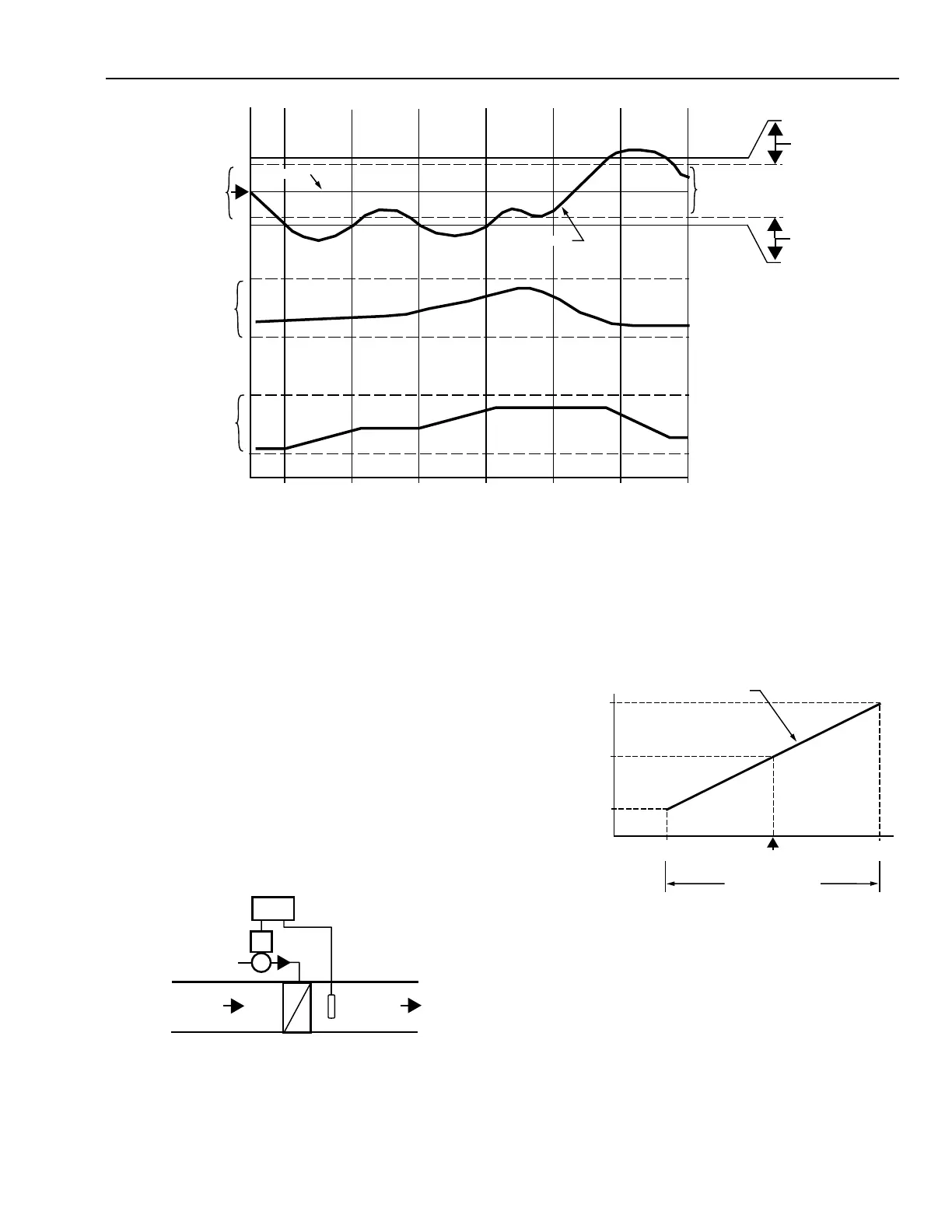
Fig. 30. Floating Control.
VALVE
CONTROLLER
SENSOR
CHILLED
WATER
RETURN
AIR
DISCHARGE
AIR
COIL
C2718
PROPORTIONAL CONTROL
General
Proportional control proportions the output capacity of the
equipment (e.g., the percent a valve is open or closed) to match
the heating or cooling load on the building, unlike two-position
control in which the mechanical equipment is either full on or
full off. In this way, proportional control achieves the desired
heat replacement or displacement rate.
In a chilled water cooling system, for example (Fig. 31), the
sensor is placed in the discharge air. The sensor measures the
air temperature and sends a signal to the controller. If a
correction is required, the controller calculates the change and
sends a new signal to the valve actuator. The actuator repositions
the valve to change the water flow in the coil, and thus the
discharge temperature.
Fig. 31. Proportional Control Loop.
In proportional control, the final control element moves to a
position proportional to the deviation of the value of the
controlled variable from the setpoint. The position of the final
control element is a linear function of the value of the controlled
variable (Fig. 32).
T1 T2 T3 T4 T5 T6
TIME
NO LOAD
FULL LOAD
CLOSED
OPEN
DAMPER
POSITION
DEADBAND
C2094
LOAD
OFF
OFF
ON
ON
“CLOSE”
SWITCH
DIFFERENTIAL
“OPEN”
SWITCH
DIFFERENTIAL
T7
CONTROLLER
CONTROL POINT
SETPOINT
Fig. 32. Final Control Element Position as a
Function of the Control Point (Cooling System).
The final control element is seldom in the middle of its range
because of the linear relationship between the position of the
final control element and the value of the controlled variable.
In proportional control systems, the setpoint is typically the
middle of the throttling range, so there is usually an offset
between control point and setpoint.
22.5 23 23.5 24 24.5
100%
OPEN
50%
OPEN
CLOSED
POSITION OF FINAL
CONTROL ELEMENT
ACTUATOR
POSITION
CONTROL POINT (°C)
THROTTLING RANGE
C3983
 Loading...


