PNEUMATIC CONTROL FUNDAMENTALS
ENGINEERING MANUAL OF AUTOMATIC CONTROL
65
construction (Fig. 10) and are used to amplify, reverse, average,
select, and switch controller outputs before being sent to valve
and damper actuators.
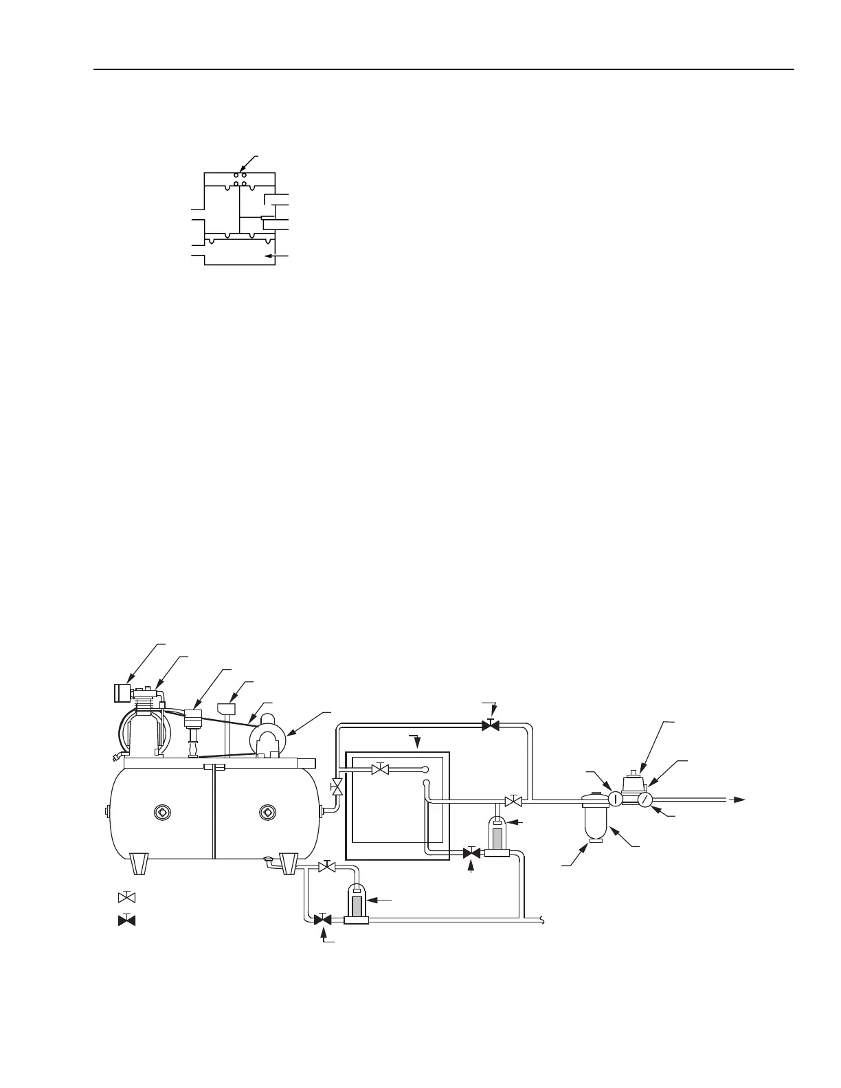
AIR COMPRESSOR
The air compressor provides the power needed to operate
all control devices in the system. The compressor maintains
pressure in the storage tank well above the maximum required
in the control system. When the tank pressure goes below a
minimum setting (usually 480 to 620 kPa), a pressure switch
starts the compressor motor. When the tank pressure reaches a
high-limit setting, the pressure switch stops the motor. A
standard tank is typically large enough so that the motor and
compressor operate no more than 50 percent of the time, with
up to twelve motor starts per hour.
AIR DRYER
MOTOR
INTAKE FILTER
COMPRESSOR
PRESSURE SWITCH
HIGH PRESSURE SAFETY RELIEF VALVE
DRIVE BELT
STORAGE
TANK
NORMALLY OPEN
SERVICE/TEST VALVE
NORMALLY CLOSED
SERVICE/TEST VALVE
C2617-2
HIGH-PRESSURE
GAGE
DRAIN
COCK
PRESSURE
REDUCING
VALVE
SAFETY REFIEF VALVE
LOW-PRESSURE GAGE
MAIN AIR
TO SYSTEM
TEST COCK
TEST COCK
AUTO TRAP
AUTO
SEPARATOR
FILTER/TRAP
SERVICE
BYPASS
VALVE
PIPED TO DRAIN
SUBMICRON
FILTER
Fig. 11. Typical Air Supply.
The controlling pressure is connected at the pilot port (P),
and pressures to be switched are connected at the normally
connected port (O) or the normally disconnected port (X). The
operating point of the relay is set by adjusting the spring pressure
at the top of the relay.
When the pressure at the pilot port reaches the relay operating
point, it pushes up on the diaphragm in the control chamber
and connects pressure on the normally disconnected port (X)
to the common port as shown. If the pilot pressure falls below
the relay setpoint, the diaphragm moves down, blocks the
normally disconnected (X) port, and connects the normally
connected port (O) to the common port.
AIR SUPPLY EQUIPMENT
GENERAL
A pneumatic control system requires a supply of clean, dry,
compressed air. The air source must be continuous because
many pneumatic sensors, controllers, relays, and other devices
bleed air. A typical air supply system includes a compressor,
an air dryer, an air filter, a pressure reducing valve, and air
tubing to the control system (Fig. 11).
The following paragraphs describe the compressor, filter,
pressure reducing valves, and air drying techniques. For
information on determining the moisture content of compressed
air, refer to the General Engineering Data section.
COMMON
PORT
P
PILOT
PORT
CONTROL
CHAMBER
X
O
NORMALLY
CONNECTED PORT
NORMALLY
DISCONNECTED PORT
C2608
SPRING
Fig. 10. Typical Switching Relay.
 Loading...


