ENGINEERING MANUAL OF AUTOMATIC CONTROL
CHILLER, BOILER, AND DISTRIBUTION SYSTEM CONTROL APPLICATIONS
371
CONTROL PRINCIPLES FOR STEAM
HEATING DEVICES
GENERAL
To control a steam supplied device, the system design should
include valves and other equipment required to produce the
amount of heat needed at design conditions. In addition, the
system should be capable of controlling a steady flow of heat
directly related to the demands of the thermostat or other
controller at load conditions from 0 to 100 percent.
To design a steam system that is capable of controlling the
various radiators and coils in a building, the pressure relationships
between the various elements of a steam heating system must be
analyzed under various load and system conditions.
MODULATING STEAM COIL PERFORMANCE
Figures 114 and 115 show a steam coil supplied from a
135 kPa steam main, controlled by an oversized modulating
valve (Fig. 114) or a correctly sized modulating valve
(Fig. 115), and discharging condensate to the return through
a trap. The figures demonstrate the importance of proper sizing
of the modulating valve and the ability of the valve to control
the output of the coil. Refer to the Valve Selection and Sizing
section for valve sizing procedures.
Low pressure steam systems operate on pressures ranging from
100 kPa to 200 kPa. The steam main pressures are usually under
170 kPa and the returns are vented to the atmosphere. To maintain
the return main pressures at 100 kPa, an air vent releases the air
from the system when steam is present and allows it to return to
the system when steam is not present. These vents do not allow
steam to escape. A sealed chamber (bellows) within the vent
contains a volatile liquid which vaporizes or condenses when
temperature changes. This causes the valve to close when steam
is present preventing the discharge of steam from the system.
Since all of the air in a steam system may not be forced out
through the radiator vents, it is necessary to provide auxiliary
vents at the ends of the steam mains and in the returns to ensure
air removal from the system. These vents are larger than radiator
vents and are referred to as quick vents.
VARIABLE VACUUM RETURN SYSTEMS
In a variable vacuum steam system, also called a sub-
atmospheric steam system, the operating pressures range from
34 kPa (absolute) to 200 kPa. The principle of water boiling at
reduced temperatures in a vacuum is the basis of a variable vacuum
steam system. In an atmospheric-return low-pressure steam
system, when the thermostat turns the burner off, boiling ceases
as soon as the temperature of the water drops to 100°C. In a
variable vacuum system, boiling continues until the water
temperature drops to the boiling point of the vacuum pressure
created by the condensation of steam in the system. This means
that steam is continuously supplied to the radiator at a decreasing
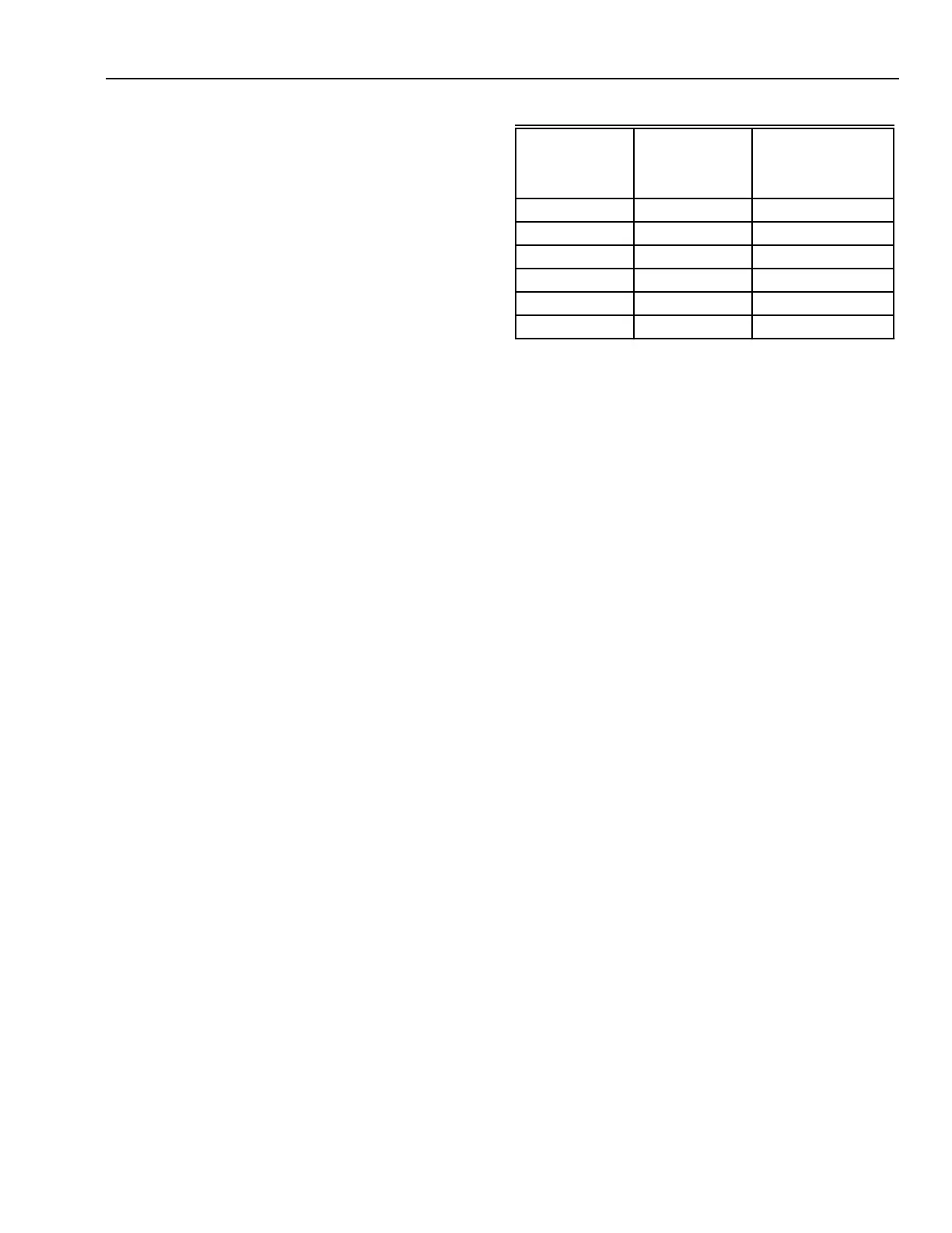
temperature until the limit of induced vacuum is reached. Table 7
shows reduced heat output from radiators in a vacuum system.
To operate successfully, the system must be air tight. Variable
vacuum systems use nonreturn vents which allow air to leave the
system but none to return. A nonreturn vent is similar to the low
pressure steam vent with a small check disc that closes to prevent
inflow of air to the system when the pressure drops below
atmospheric.
The period of time that a variable vacuum system can operate
in the vacuum range is dependent upon the tightness of the
connections of the system. Once a variable vacuum system has
built up a vacuum, it is possible for the burner to operate at
frequent enough intervals to keep the system within the vacuum
range during mild and intermediate load conditions. Since a
low steam temperature is maintained, the radiator temperature
is low. By keeping the radiator warm for longer periods of time,
temperature stratification in the space is reduced.
Table 7. Heat Output versus Steam Pressure for Coils.
Saturated
Steam
Pressure
kPa
Steam
Temp,
˚C
Typical Steam
Coil
a
With 5°C
Entering Air
kJ/hr
200 120.2 119100
150 111.4 110400
101.3 100.0 101500
100 99.6 99800
90 96.7 97200
80 93.5 95100
a
2 row steam distributing coil, 3 fins per
centimeter, 2.5 meters per second face velocity,
and 0.22 square meter face area
 Loading...


