ENGINEERING MANUAL OF AUTOMATIC CONTROL
CONTROL FUNDAMENTALS
29
In terms of heating and air conditioning, a large office area
containing desks, file cabinets, and office machinery has more
capacitance than the same area without furnishings. When the
temperature is lowered in an office area over a weekend, the
furniture loses heat. It takes longer to heat the space to the
comfort level on Monday morning than it does on other
mornings when the furniture has not had time to lose as much
heat. If the area had no furnishings, it would heat up much
more quickly.
The time effect of capacitance determines the process reaction
rate, which influences the corrective action that the controller
takes to maintain process balance.
Resistance
Resistance applies to the parts of the process that resist the
energy (or material) transfer. Many processes, especially those
involving temperature control, have more than one capacitance.
The flow of energy (heat) passing from one capacitance through
a resistance to another capacitance causes a transfer lag (Fig. 47).
Fig. 47. Schematic of Heat Flow Resistance.
A transfer lag delays the initial reaction of the process. In
temperature control, transfer lag limits the rate at which the
heat input affects the controlled temperature. The controller
tends to overshoot the setpoint because the effect of the added
heat is not felt immediately and the controller calls for still
more heat.
The office described in the previous example is comfortable
by Monday afternoon and appears to be at control point.
However, the paper in the middle of a full file drawer would
still be cold because paper has a high thermal resistance. As a
result, if the heat is turned down 14 hours a day and is at comfort
level 10 hours a day, the paper in the file drawer will never
reach room temperature.
An increase in thermal resistance increases the temperature
difference and/or flow required to maintain heat transfer. If the
fins on a coil become dirty or corroded, the resistance to the
transfer of heat from one medium to the other medium increases.
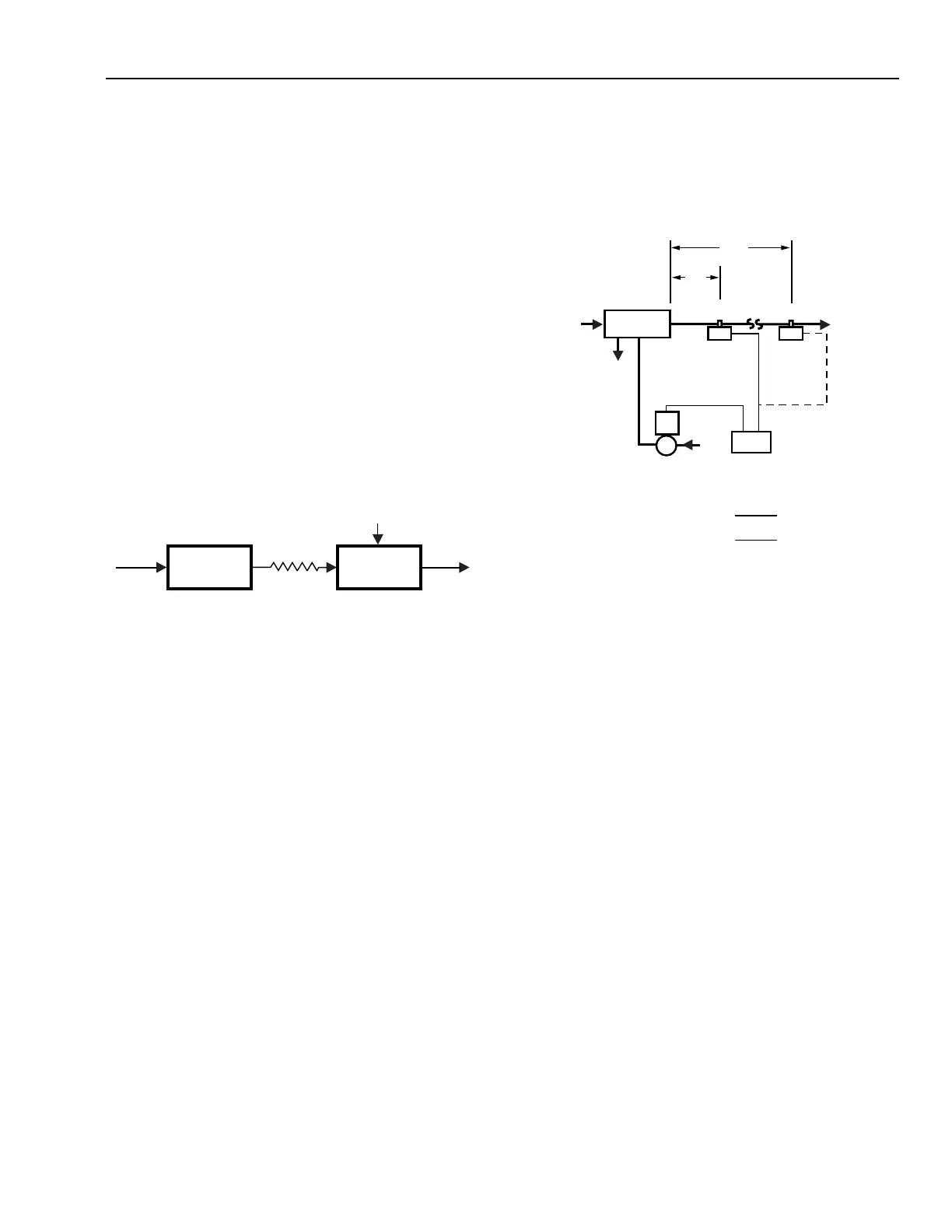
Dead Time
Dead time, which is also called “transportation lag”, is the
delay between two related actions in a continuous process where
flow over a distance at a certain velocity is associated with
energy transfer. Dead time occurs when the control valve or
sensor is installed at a distance from the process (Fig. 48).
STEAM
IN
HEAT CAPACITY
OF STEAM
IN COILS
RESISTANCE TO
HEAT FLOW
(E.G., PIPES, TANK WALLS)
COLD WATER
IN
HEAT CAPACITY
OF WATER
IN TANK
HOT
WATER
OUT
C2078
Fig. 48. Effect of Location on Dead Time.
Dead time does not change the process reaction
characteristics, but instead delays the process reaction. The
delay affects the system dynamic behavior and controllability,
because the controller cannot initiate corrective action until it
sees a deviation. Figure 48 shows that if a sensor is 8 meters
away from a process, the controller that changes the position
of the valve requires two seconds to see the effect of that change,
even assuming negligible capacitance, transfer, and
measurement lag. Because dead time has a significant effect
on system control, careful selection and placement of sensors
and valves is required to maintain system equilibrium.
CONTROL APPLICATION GUIDELINES
The following are considerations when determining control
requirements:
— The degree of accuracy required and the amount of
offset, if any, that is acceptable.
— The type of load changes expected, including their
size, rate, frequency, and duration.
— The system process characteristics, such as time
constants, number of time lag elements, and
reaction rate.
VALVE
HWS
PROCESS
CONTROLLED
MEDIUM IN
HWR
24 FT
2 FT
CONTROLLED
MEDIUM OUT
SENSOR AT
LOCATION 1
SENSOR AT
LOCATION 2
CONTROLLER
VELOCITY OF CONTROLLED MEDIUM: 12 FT/S
DEAD TIME FOR SENSOR AT LOCATION 1: = 0.166 SEC
DEAD TIME FOR SENSOR AT LOCATION 2: = 2.0 SEC
2 FT
12 FT/S
24 FT
12 FT/S
C2079
 Loading...


