INDIVIDUAL ROOM CONTROL APPLICATIONS
ENGINEERING MANUAL OF AUTOMATIC CONTROL
399
ABBREVIATIONS
The following abbr eviations ar e used:
BMS — Building Management System
AT U — Air Terminal Unit
VAV — Variable Air Volume
ZEB — Zer o Ener gy Band
DDC — Direct Digital Control
CAV — Constant Air Volume
AIR TERMINAL UNIT CONTROL
Air ter minal units (A TUs) r egulate the quantity and/or
temper atur e of conditioned air deli vered to sa tisfy the
temper atur e requir ements of a r oom or space . ATUs ar e
classified by air handling system design and ar e available in
man y configur ations. F or inf ormation on the air suppl y to ATUs,
refer to the Air Handling System Contr ol Applica tions section
and the Building Airflow System Contr ol Applica tions section.
ATU contr ols can be as basic as a r oom sensor contr olling a
damper or as comple x as a r oom sensor and an airf low sensor
oper ating a damper and a r eheat coil valve. In all cases, an
individual r oom contr ol applica tion contr ols the environment
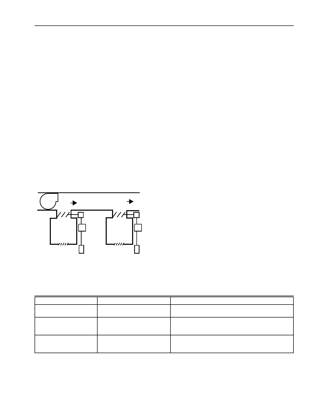
of the r oom or space . Figur e 1 shows basic indi vidual r oom
contr ol with an ATU.
FAN
ATU
ATU
GRILLE GRILLE
WALL
MODULE
WALL
MODULE
DAMPER
ACTUATOR
TO OTHER
SPACES
CONDITIONED
AIR
CONTROLLER
CONTROLLER
C2399-1
SPACE 2SPACE 1
Fig. 1. Basic Individual Room Control.
VARIABLE AIR VOLUME ATU
A var iable air v olume (VAV) ATU contr ols the cooling of a
space b y var ying the amount of conditioned air supplied r ather
than c hang ing the temper atur e of the conditioned air . Most VAV
systems pr ovide ener gy savings by reducing the load on the
central fan when cooling loads are less than design and avoid
reheating cooled air .
A system designed to r educe overall system airf low as ATUs
shut do wn offers the greatest ener gy savings because system
fans and f an motor s oper ate at lighter loads. These par agraphs
descr ibe the oper ation of VAV ATUs in single-duct and dual-
duct air handling systems.
PRESSURE-DEPENDENT AND
PRESSURE-INDEPENDENT ATU
A Pr essur e-dependent ATU is affected b y chang ing duct sta tic
pressures. It ma y have mechanical minim um and maxim um
airf low limits.
A pr essure-independent ATU automa tically adjusts to duct
static pr essure chang es because it contains airf low sensor s and
contr oller s to compensa te for pr essur e chang es. When used with
DDC systems, the pr essure-independent ATU ma y be
programmed to change the airflow delivered based on the
operating mode . Table 1 descr ibes some modes with the
associated command and comments on the reasoning.
Table 1. AHU Operating Modes and Associated ATU Airflow Settings.
Mode Command Comments
Smoke Purge Mode All associated boxes to 82%
maximum airflow.
AHU was sized with diversity such that the total box
maximum airflows exceed the fan design airflow.
Thermal or IAQ Pre-Purge All the boxes to 50% maximum
airflow.
Take advantage of the fan motor power cube root
relationship to airflow (fan runs twice as long at one
eighth the motor power).
Preoccupancy Cool Down Perimeter boxes to 50%
maximum airflow and the interior
boxes to 80% maximum airflow.
Reduce the fan energy per cubic meter of air delivered
by half, match the fan-to-chiller load for better chiller
efficiency and for better dehumidification.
 Loading...


