ENGINEERING MANUAL OF AUTOMATIC CONTROL
CHILLER, BOILER, AND DISTRIBUTION SYSTEM CONTROL APPLICATIONS
368
STEAM DISTRIBUTION SYSTEMS
STEAM PIPING MAINS
Steam piping mains must carry steam to all parts of the
system allowing a minimum amount of condensate (heat loss)
to form, must provide adequate means to collect the condensate
that does form, and must prevent water pockets that can cause
water hammer.
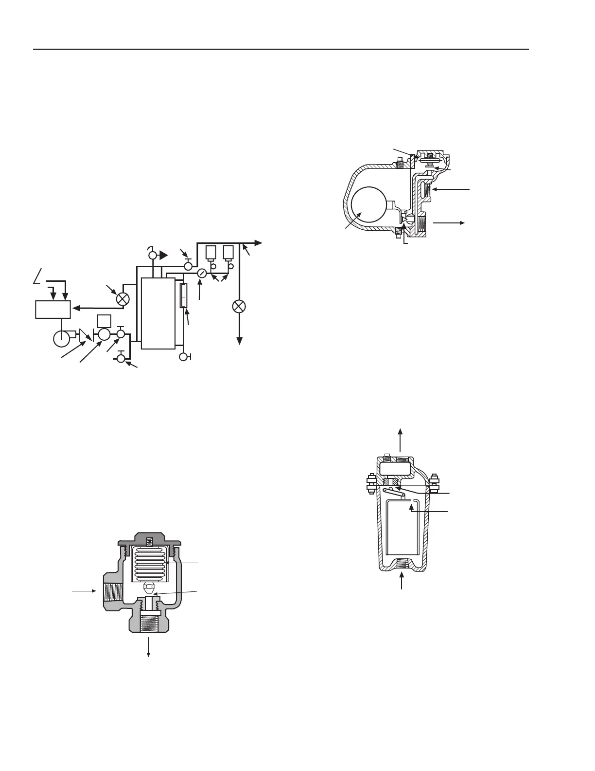
Figure 102 shows typical connections at the boiler. The
system shown uses a condensate (receiver) tank and pump.
Condensate returns must be properly pitched for gravity
condensate flow and properly insulated so heat contained in
the condensate is not wasted.
The float and thermostatic trap (Fig. 104) can handle large
amounts of air and condensate and is commonly used on steam
coils in air handling systems. In this trap, the thermostatic
element passes air until it senses steam at which time it closes
the valve. As condensate water builds up in the trap, the float
valve opens to discharge condensate into the return line.
Fig. 102. Typical Boiler Connections.
STEAM TRAPS
Traps remove condensate from the steam mains and all steam-
using equipment without allowing steam to enter the return
mains. The thermostatic trap (Fig. 103) is most common for
trapping condensate from radiators and convectors in low
pressure systems. When the thermostatic element senses steam
temperature, it closes the valve. The valve remains closed until
the element cools.
{
BOILER
BLOWDOWN
VALVE
LOW WATER
CUTOFF, PUMP
CONTROL AND
GAUGE GLASS
TO
RECEIVER
TANK
STEAM
PRESSURE
GAUGE
PRESSURE
CONTROLS
F & T
TRAP
STEAM
MAIN
STOP
VALVE
RELIEF
VALVE
F & T
TRAP
HIGH LEVEL
"SPILL"
CONDENSATE
RETURNS
RECEIVER
TANK
PUMP
CHECK
VALVE
SOLENOID
VALVE
(OPTIONAL)
STOP
VALVE
C2923
Reprinted by permission from the ASHRAE Handbook—
1996 Systems and Equipment
Fig. 103. Thermostatic Trap.
THERMOSTATIC
ELEMENT
VALVE
OUTLET
INLET
M15070
Reprinted by permission from the ASHRAE Handbook—
1996 Systems and Equipment
Fig. 104. Float and Thermostatic Trap.
Another common trap is the inverted bucket (Fig. 105) which
has a large capacity (up to 7 kg/s) for discharging condensate.
In the bucket trap, the bucket is normally down so the valve is
open. The bucket is normally about two-thirds full of condensate
so, when condensate enters the trap, it flows around the bucket
and through the trap. As air or steam enters the bucket, the
bucket rises, closing the valve when the condensate level drops
to about one-third full. Air escapes slowly through the air vent
and steam condenses so the bucket drops, opening the outlet.
THERMOSTATIC
DISC ELEMENT
FLOAT
VALVE AND
ORIFICE
VALVE
INLET
OULET
FLOAT
M15071
Reprinted by permission from the ASHRAE Handbook—
1996 Systems and Equipment
Fig. 105. Inverted Bucket Trap.
Kinetic traps, shown in Figures 106, 107, and 108, are used
in high pressure systems. They rely on flow characteristics of
steam and condensate and on the fact that condensate
discharging to a lower pressure contains more heat than
necessary to maintain its liquid state.
OUTLET
VALVE AND
ORIFICE
AIR
INLET
M15072
 Loading...


