ENGINEERING MANUAL OF AUTOMATIC CONTROL
INDIVIDUAL ROOM CONTROL APPLICATIONS
422
In some hea t pumps, a minim um off timer pr events a
compr essor r estar t for thr ee to five minutes. After shutdo wn,
heat pump operation must not resume until pressures equalize
between the suction and disc har ge sides of the compr essor. Shor t
cycling the hea t pump ma y result in compr essor dama ge.
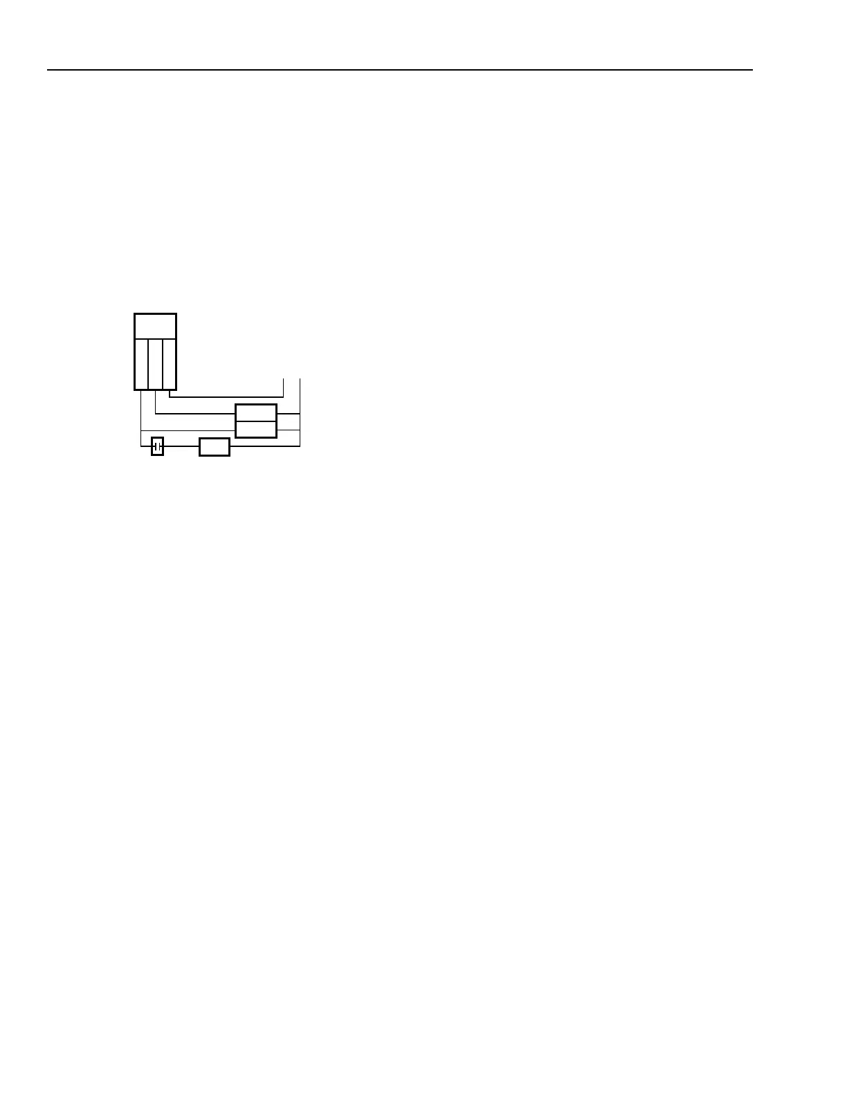
A two-stage, high-speed compr essor can pr ovide capacity
contr ol for maxim um hea t pump ef ficiency. The r oom ther mosta t
contr ols the indi vidual compr essor sta ges. The ther mosta t second
stage contr ols the auxiliar y heat (for air -sour ce heat pumps) and
compr essor sta ge two. When the outdoor ther mosta t contact c loses
as outdoor temper atur e falls to its setpoint, the auxiliar y heat
ener gizes with the compr essor (F ig. 38).
CONTROL LOOPS
Heat pumps can use a v ar iety of methods to c hang e between
cooling and hea ting, including a tw o-position r oom ther mosta t
and man ual c hang eover.
Assuming automa tic chang eover betw een heating and
cooling, on a r ise in space temper atur e, a two-position r oom
ther mosta t senses the temper atur e r ise and c ycles the hea t pump
in the cooling mode . When space temper atur e falls below the
deadband , the first sta ge of heating cycles the compr essor in
the hea ting mode . A fur ther dr op in space temper atur e br ings
on additional thermostat heating stages to turn on supplemental
electric resistance heaters.
In some hea t pumps, the chang eover valve cycles with the
compressor in either the heating or cooling mode. In others,
the chang eover valve remains in the hea ting or cooling position
as long as space temperature is in the appropriate range.
Wher e a centr al water plant pr ovides hea ting/cooling sour ce
water for the hea t pumps, water contr ol is often pr ovided to
conser ve water w hen the hea t pump c ycles off and w hen the
water temper atur e is excessive for the load . Valves may be
refrigerant pressure (may be furnished with the heat pump) or
temper atur e contr olled. Temper atur e contr olled valves must
close when the compr essor is off, but must ha ve a minim um
open position anytime the heat pump operates in order to keep
water f low acr oss the water sensor .
Heat pump system controls must be carefully coordinated
with the hea t pump man ufactur er and the w ater plant system
(on air -to-water hea t pumps).
Fig. 38. Heat Pump Staging.
Defrost cycling is typicall y used when outdoor temper atur es
are below 7 °C, because the outdoor coil may operate below
freezing and frost can form on the coil when the unit is in the
heating mode. Frost inhibits airflow through the heat pump and
degr ades unit perf ormance . To remove the fr ost, the hea t pump
momentar ily switches to the cooling mode . Hot gas from the
compressor is directed to the outdoor coil, and the frost melts.
Typically the unit c ycles every 90 minutes for four to eight
minutes to defrost. Instead of time-initiated defrost, some
models use demand defr ost, which cycles to the cooling mode
by measur ing chang es in the airf low acr oss the outdoor coil.
THERMOSTAT
HEAT 2
HEAT 1
COMMON
OUTDOOR AIR
THERMOSTAT
AUXILIARY
HEAT
STAGE 1
STAGE 2
HEAT PUMP
POWER
C3023
 Loading...


