ENGINEERING MANUAL OF AUTOMATIC CONTROL
BUILDING AIRFLOW SYSTEM CONTROL APPLICATIONS
276
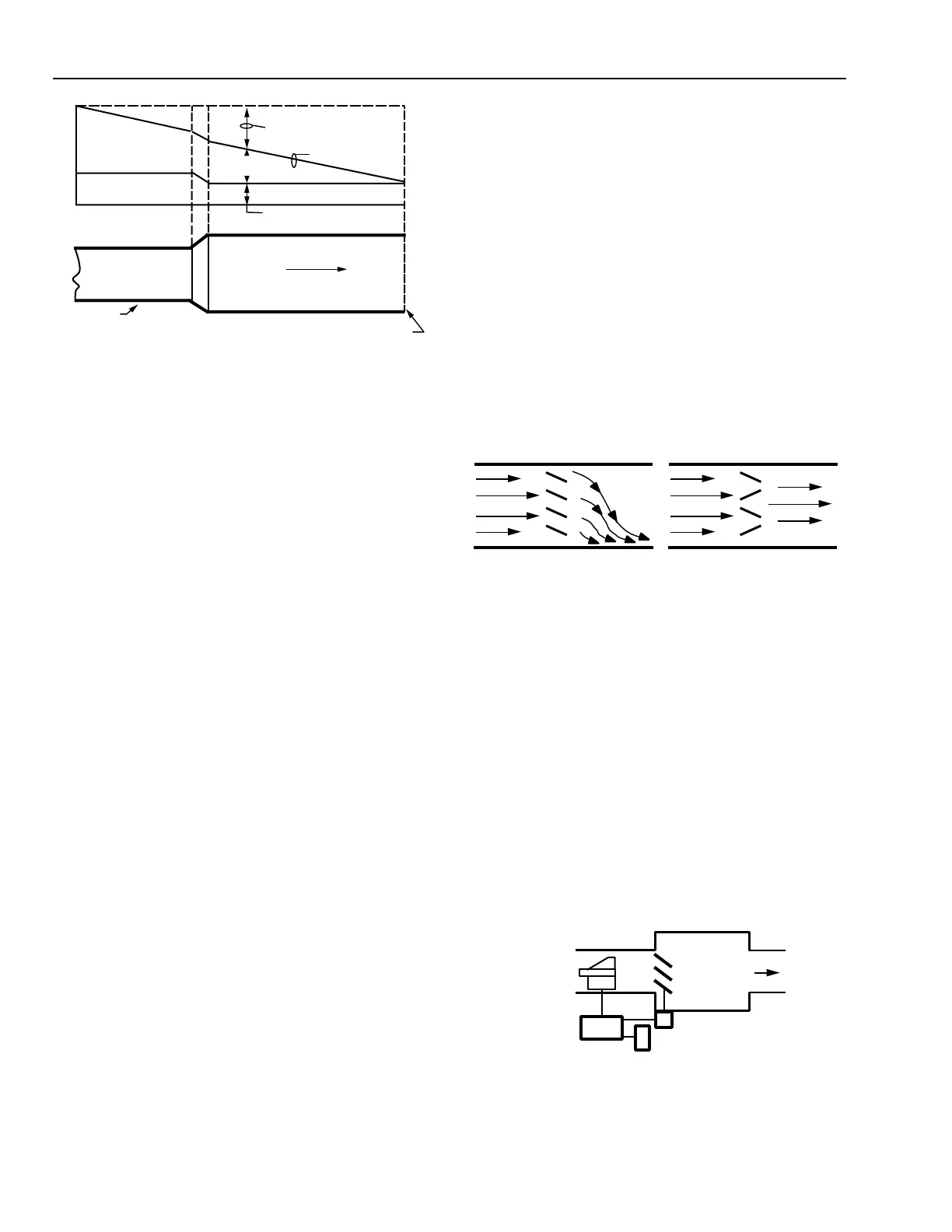
TOTAL PRESSURE
VELOCITY
PRESSURE
DIRECTION
OF AIRFLOW
AIR DUCT
OPEN END
OF DUCT
C2646
FRICTION LOSS
STATIC
PRESSURE
PRESSURE
Fig. 11. Pressure Changes in a Duct
with Outlet Larger than Inlet.
The size of a duct required to transport a given quantity of
air depends on the air pressure available to overcome the friction
loss. If a small total pressure is available from the fan, the duct
must be large enough to avoid wasting this pressure as friction
loss. If a large total pressure is available from the fan, the ducts
can be smaller with higher velocities and higher friction losses.
Reducing the duct size in half increases the velocity and the
friction loss increases.
In most low pressure airflow systems, the velocity component
of the total pressure may be ignored because of its relative size.
For example, if a supply fan delivers 5 m
3
/s at 500 Pa static
pressure in a supply duct that is 1m x 1.25m (or 1.25m
2
), the
Velocity (V = Q ÷ A) is 5 m
3
/s ÷ 1.25m
2
or 4 m/s. The Velocity
Pressure [VP = (V ÷ 1.3)
2
] is (4 ÷ 1.3)
2
= 9.47. The velocity
pressure is 1.9 percent of the static pressure at the fan [(9.47 ÷
500) x 100 = 1.9%].
In most high pressure airflow systems, the velocity pressure
does become a factor. For example, if a supply fan delivers
5 m
3
/s at 1500 Pa static pressure in a round supply duct that is
0.6m in diameter or 0.027m
2
, the Velocity (V = Q ÷ A) is 5 m
3
/s
÷ 0.28m
2
or 17.9 m/s. The Velocity Pressure [VP = (V ÷ 1.3)
2
] is
(17.9 ÷ 1.3)
2
or 190 Pa. The velocity pressure is 12.7 percent of
the static pressure at the fan [(190 ÷ 1500) x 100 = 12.7%].
EFFECTS OF FITTINGS
Ducts are equipped with various fittings such as elbows,
branch takeoffs, and transitions to and from equipment which
must be designed correctly to prevent pressure losses.
In elbows, the air on the outside radius tends to deflect around
the turn. The air on the inside radius tends to follow a straight
path and bump into the air on the outer edge. This causes eddies
in the air stream and results in excessive friction losses unless
prevented. Turning vanes are often used in elbows to reduce
the friction loss. In addition, they provide more uniform and
parallel flow at the outlet of the elbow.
In transitions to and from equipment an attempt is made to
spread the air evenly across the face of the equipment. If the
diverging section into the equipment has too great an angle,
splitters are often used. The splitters distribute the air evenly and
reduce friction losses caused by the air being unable to expand as
quickly as the sides diverge. In converging sections friction losses
are much smaller, reducing the requirement for splitters.
EFFECTS OF DAMPERS
Dampers are often used in ducts for mixing, for face and
bypass control of a coil, for volume control, or for numerous
other air volume controls. Figure 12 shows the velocity profile
in a straight duct section. Opposed blade dampers are
recommended where there are other system components
downstream of the damper such as coils or branch takeoffs as
they do not adversly distort the air velocity profile. Parallel
blade damper can be used where the airflow discharges into a
free space or a large plenum.
PARALLEL BLADE
DAMPER ILLUSTRATING
DIVERTED FLOW
OPPOSED BLADE
DAMPER ILLUSTRATING
NON - DIVERTED FLOW
C2652
Fig. 12. Velocity Profile of Parallel Blade vs
Opposed Blade Damper.
EFFECTS OF AIR TERMINAL UNITS
A variety of air terminal units are available for air handling
systems. For VAV systems, the single duct, Variable Constant
Volume (VCV), throttling type air terminal unit (Fig. 13) is
typically used. With this device, the space thermostat resets the
setpoint of an airflow controller, varying the volume of
conditioned air to the space as required. Since a number of
these units are usually connected to the supply duct, it is the
collective requirements of these units that actually determines
the airflow in the main supply duct. In this type of system, the
supply fan is controlled to maintain a constant static pressure
at a point in the duct system so there is sufficient supply air for
all of the air terminal units.
AIR
TERMINAL
UNIT
AIRFLOW
CONTROLLER
ACTUATOR
THERMOSTAT
C2653
AIRFLOW
SENSOR
Fig. 13. Single Duct, Variable Constant
Volume Air Terminal Unit.
 Loading...


