MICROPROCESSOR-BASED/DDC FUNDAMENTALS
137ENGINEERING MANUAL OF AUTOMATIC CONTROL
CONTROLLER SOFTWARE
Although microprocessor-based controller hardware governs,
to some extent, how a controller is applied, software determines
the functionality. Controller software falls basically into two
categories:
1. Operating software which controls the basic operation
of the controller.
2. Application software which addresses the unique control
requirements of specific applications.
OPERATING SOFTWARE
Operating software is normally stored in nonvolatile memory
such as ROM or PROM and is often referred to as firmware.
Operating software includes the operating system (OS) and
routines for task scheduling, I/O scanning, priority interrupt
processing, A/D and D/A conversion, and access and display
of control program variables such as setpoints, temperature
values, parameters, and data file information. Tasks are
scheduled sequentially and interlaced with I/O scanning and
other routine tasks in such a way as to make operation appear
almost simultaneous. However, an external event such as an
alarm or a request to execute and energy management program,
can require that normal operations be suspended until the higher
priority task is serviced. These requests are processed by priority
interrupt software. The interrupt causes the current operation
to cease, and all data held in registers and accumulators pertinent
to the interrupted programs is temporarily stored in memory.
Once the interrupt request is processed, all data is returned to
the proper registers, and the program resumes where it left off.
Multiple levels or prioritized interrupts are provided. The effect
of these interrupts is transparent to the application that the
controller is controlling.
APPLICATION SOFTWARE
Application software includes direct digital control, energy
management, lighting control, and event initiated programs plus
other alarm and monitoring software typically classified as
building management functions. The system allows application
programs to be used individually or in combination. For
example, the same hardware and operating software can be used
for a new or existing building control by using different
programs to match the application. An existing building, for
example, might require energy management software to be
added to the existing control system. A new building, however,
might require a combination of direct digital control and energy
management software.
DIRECT DIGITAL CONTROL SOFTWARE
DDC software can be defined as a set of standard DDC
operators and/or high-level language statements assembled to
accomplish a specific control action. Key elements in most
direct digital control programs are the PID and the enhanced
EPID and ANPID algorithms. For further information, refer
to the Control Fundamentals section.
While the P, PI, PID, EPID, and ANPID operators provide
the basic control action, there are many other operators that
enhance and extend the control program. Some other typical
operators are shown in Table 1. These operators are computer
statements that denote specific DDC operations to be performed
in the controller. Math, time/calendar, and other calculation
routines (such as calculating an enthalpy value from inputs of
temperature and humidity) are also required.
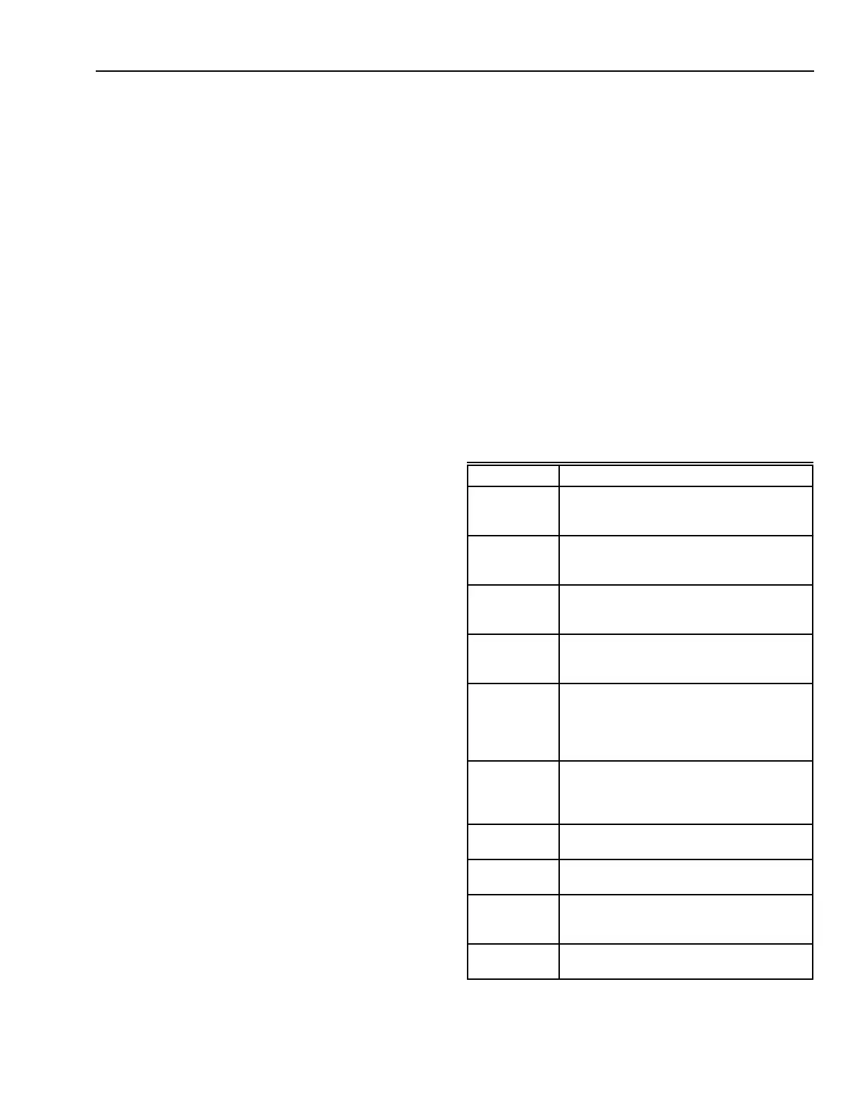
Table 1. Typical DDC Operators.
Operator Description
Sequence Allows several controller outputs to be
sequenced, each one operating over a full
output range.
Reversing Allows the control output to be reversed to
accommodate the action of a control valve
or damper actuator.
Ratio Translates an analog output on one scale
to a proportional analog output on a
different scale.
Analog
controlled
digital output
Allows a digital output to change when an
analog input reaches an assigned value.
Also has an assignable dead band feature.
Digital
controlled
analog output
Functionally similar to a signal switching
relay. One state of the digital input selects
one analog input as its analog output; the
other state selects a second analog input
as the analog output.
Analog
controlled
analog output
Similar to the digital controlled analog
output except that the value and direction of
the analog input value selects one of the
two analog signals for output.
Maximum
input
Selects the highest of several analog input
values as the analog output.
Minimum input Selects the lowest of several analog input
values as the analog output.
Delay Provides a programmable time delay
between execution of sections of
program code.
Ramp Converts fast analog step value changes
into a gradual change.
 Loading...


