INDIVIDUAL ROOM CONTROL APPLICATIONS
ENGINEERING MANUAL OF AUTOMATIC CONTROL
407
The dotted line of F igur e 10 shows a modif ication of this str ategy
wher ein the constant v olume r equir ement is r elaxed a little to
pr ovide some VAV cooling contr ol pr ior to g oing into the hea ting/
mixing por tion of contr ol. This allows a dead band and a little
VAV cooling contr ol. This uses the same har dwar e (and cost) and
allows an easil y adjusta ble minim um airf low, up to the maxim um.
In this conf igur ation, the r oom will oper ate at the hea ting setpoint
most of the time and the lo wer the minim um airf low is set, the
more time control will be in the deadband range or at the cooling
setpoint. Rooms ma y have either high minim um airf low setpoints
or low minim um airf low setpoints.
Dual Duct Pressure Independent
Constant Volume ATU
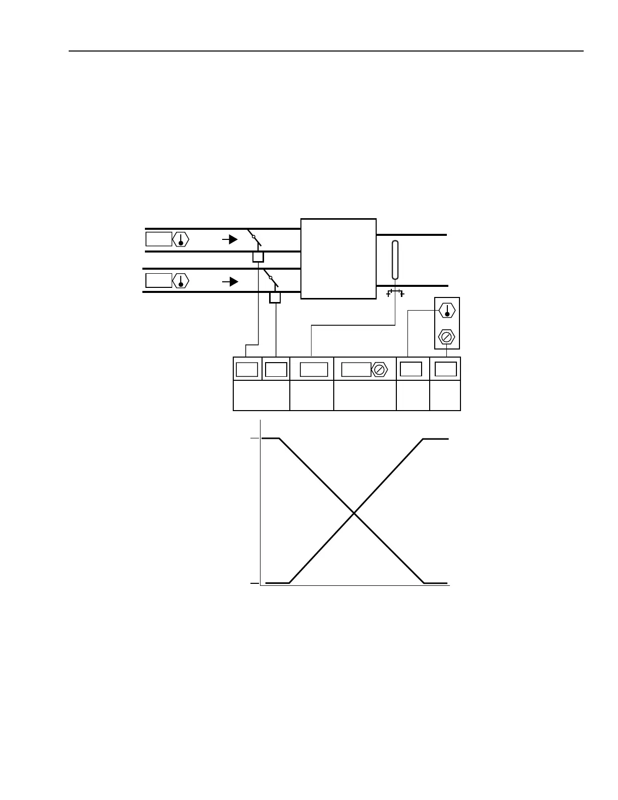
Figur e 11 shows a constant v olume pr essur e inde pendent dual
duct ATU. Modula ting the hot duct damper , up to a total f low
not to exceed the maximum airflow setpoint maintains the room
temper atur e. A constant total airf low is nor mally maintained
by modula ting the cold duct damper . With this conf igur ation,
there is no deadband and comfort is maintained by mixing hot
and cold air a t a constant total airf low. Hot and cold duct
temper atur e load r eset is very impor tant in all dual duct systems
to minimiz e ener gy waste.
Fig. 11. Dual-Duct Constant Volume Air Terminal Unit.
MAX
HEATING
LOAD
M15312
MAX
COOLING
LOAD
ZERO
AIRFLOW
(m
3
/s)
CONSTANT
AIRFLOW
SETPOINT
HOT DUCT
AIRFLOW
COLD DUCT
AIRFLOW
24 24
13
25.5
0.4550.45500 77
AIRFLOW
SETPOINT
(m
3
/s)
CURRENT
AIRFLOW
(m
3
/s)
DAMPER
PERCENT
OPEN
COOLING
SETPOINT
TEMPERATURE
WALL MODULE
HOT
DUCT
COLD
DUCT
 Loading...


