ENGINEERING MANUAL OF AUTOMATIC CONTROL
CHILLER, BOILER, AND DISTRIBUTION SYSTEM CONTROL APPLICATIONS
384
KEY POINTS
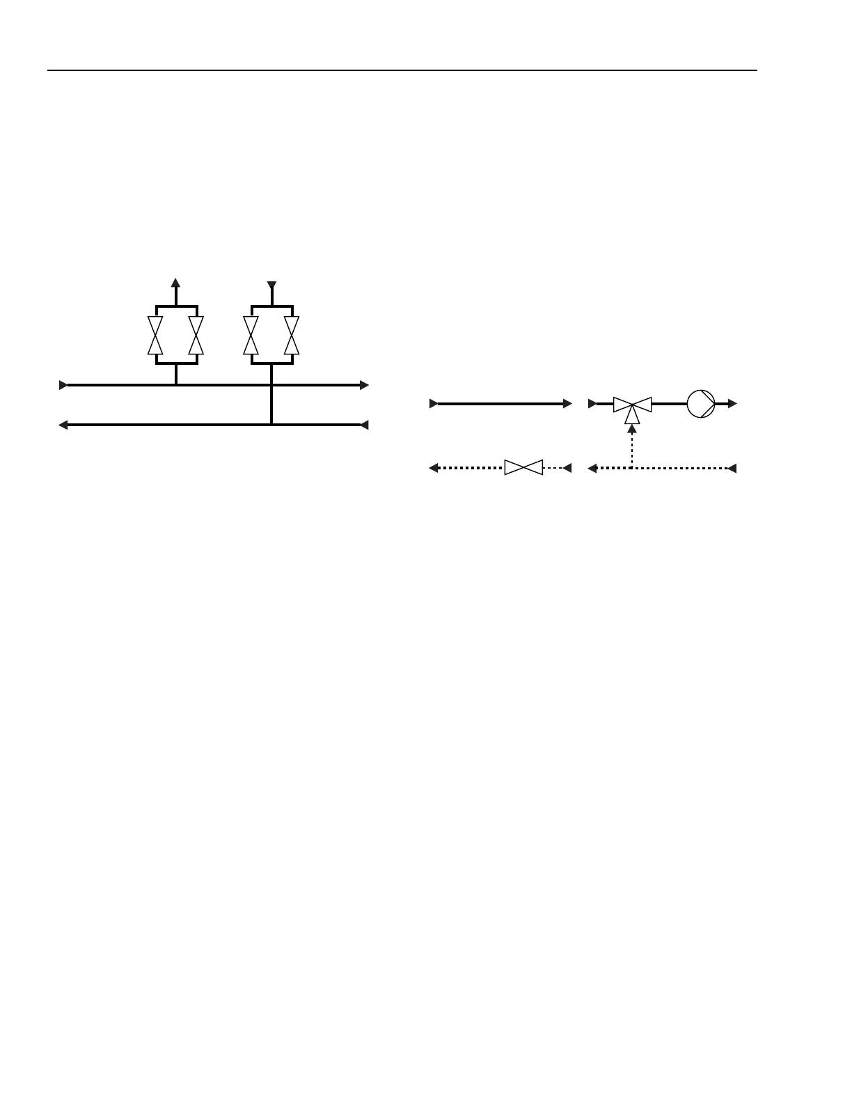
Key points are locations where pipelines branch off (Fig. 129).
They consist of valves for supply and return flow which can
separate the branch line from the main line. If a branch line is
shut down, the pressure ratio in the entire network is affected.
To prevent pressure spikes in the main system, the shutdown
must be performed slowly and carefully. Often two different
sized surge tanks in parallel are used to damp the pressure peak
during shutdown. Usually key point temperatures and pressures
are monitored.
Functional principles:
The primary side consists of the supply and return lines, plus
necessary pressure reducing, regulating, and safety equipment.
This is self-regulating equipment which provides a given
differential pressure, absolute pressure reducing, and safety
close off functions.
The heat regulation unit (Fig. 130) provides the required
temperature by controlling the primary flow (A) or by mixing
the cooled return water with supply water (B). Different
configurations with two and three way valves can be used. In
the flow control configuration a fixed speed circulating pump
increases the pressure in the return line above the supply flow
pressure. In the temperature control configuration either a jet
pump or a three way valve is used.
Fig. 129. Typical Key Point.
HEAT TRANSFER SUBSTATIONS
In general heat transfer substations link district heating
networks with the consumer. The consumer side can be either
another network or the end user.
Heat transfer can be either direct and indirect. Direct transfer
uses mixing valves, jet pumps or two way valves to supply the
heating medium directly to the consumer. Indirect substations
use heat exchangers and physically decoupled or independent
heating circuits.
Direct Heat Transfer Substations
The main parts of a direct substation are:
– Primary side.
– Heat flow regulation unit.
– Circulating pumps.
– Secondary side.
Direct heat transfer substations:
– Transfer the required heat from the supply (primary) side
to the consumer (secondary) side.
– Meter heat.
– Provide safety functions to protect consumer and
equipment against overheating, frost, and harmful agents
in hot tap water.
– Provide optimization functions to reduce energy
consumption to the lowest possible level.
Fig. 130. Two- And Three-Way Valve
Configurations for a Heat regulation Unit.
Jet pumps use the effect of injection, making a mechanical
pump unnecessary, thereby, saving electrical energy. However,
adapting and dimensioning jet pump applications to fit operating
conditions is difficult.
Control loops used in a direct substation:
– Supply flow temperature reset on outdoor air temperature.
– Return temperature limit.
– Time schedule functions.
– Night setback and frost protection.
Small Substation For Multiple Family Buildings
Figure 131 shows a typical direct heat transfer substation.
M11445
RETURN FLOW
SUPPLY FLOW
MAIN LINES
BRANCH
SURGE
TANKS
M11446
CONTROL VALVE
CIRCULATING
PUMP
THREE-WAY
MIXING VALVE
OR JET PUMP
A) FLOW CONTROL
B) TEMPERATURE CONTROL
SUPPLY LINE
RETURN LINE
 Loading...


