ENGINEERING MANUAL OF AUTOMATIC CONTROL
CHILLER, BOILER, AND DISTRIBUTION SYSTEM CONTROL APPLICATIONS
352
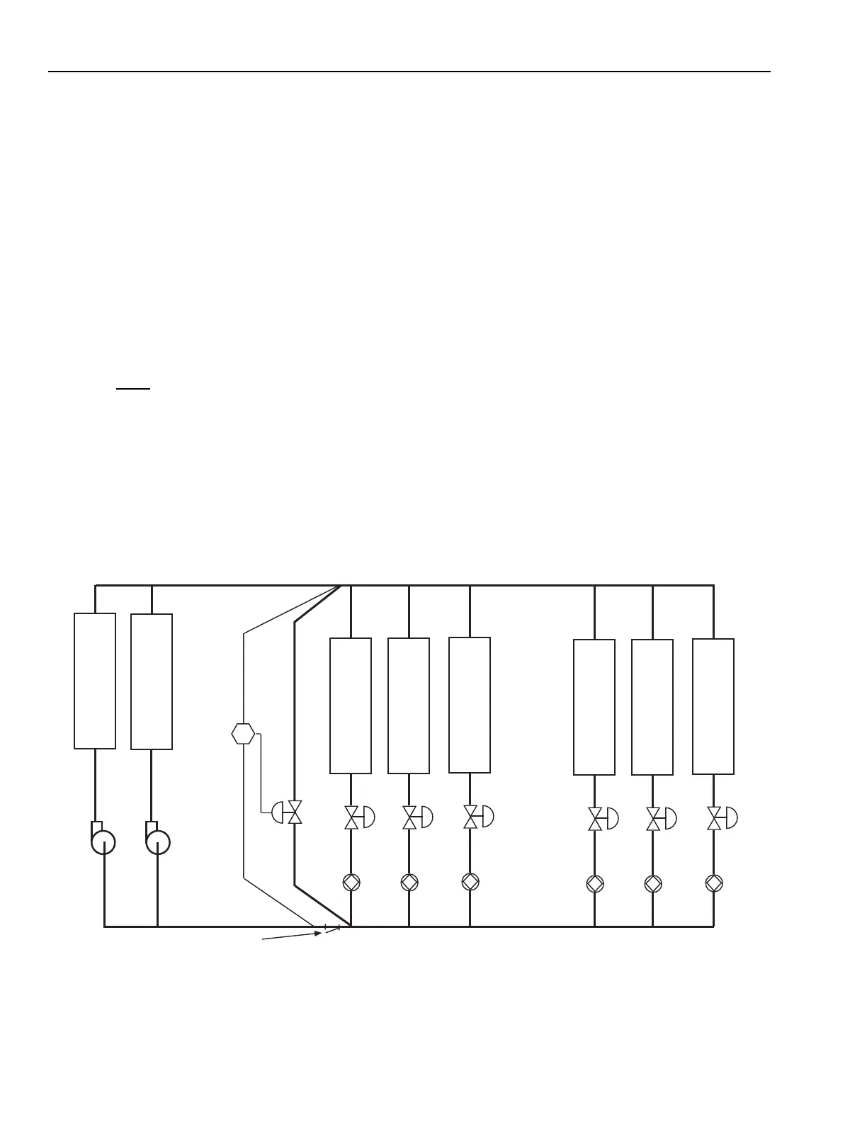
Dual Pumps, Dual Chillers, Pressure Bypass,
90 percent Chiller Flow, Direct Return
Dual chiller pressure bypass systems are popular because if
a chiller, tower, or pump fails, there is part load redundancy
and better part load efficiency.
In Figure 77, the bypass sensor and valve is in the same
location as the single chiller system (Fig. 75). The valve is sized
for approximately 37.5 L/s.
The differential pressure setpoint is the same as for the single
pump/chiller system (103.5 kPa) when both pumps are running.
When only one pump/chiller is operating, the piping between
the pump/chiller and differential pressure sensor carry a
minimum of 33.75 L/s (90 percent flow for one chiller) and the
piping friction drop falls from 12 kPa to 2.43, thus:
With digital controls, the differential pressure setpoint offset
adjustment when only one chiller/pump is operating is handled
by a software routine (dual chiller/pump setpoint plus 14.4 kPa)
invoked anytime only one pump and one chiller are operating.
One method using pneumatic controls uses two pressure
controllers with separate setpoints. The primary controller is
set at 117.24 kPa with the secondary controller set at 103.5 kPa
setpoint and configured as a low limit device during periods of
single pump/chiller operation. During periods of dual pump/
chiller operation, the 103.5 kPa setpoint controller is used alone.
AHU Valve High Differential Pressure Control
As noted in the discussion of Figure 75, the differential pressure
controlled bypass valve in constant speed pumping systems is
adequate to maintain a high flow through chillers, but does little
to prevent high differential pressures across the AHU load control
valves. In the previous example the load control valve differential
pressure varied from 24 kPa at design load to 117.24 kPa at the
single chiller, light-load mode of operation.
If it is expected that the light-load differential pressures will
exceed the load control valves close-off rating, locate a throttling
valve in the common load piping (valve V8 in Figure 78) to
reduce the load pressures while still allowing adequate pressure
to maintain chiller flows. Select either a double-seated or
balanced cage type valve for the high differential pressure.
Fig. 77. Dual Pumps, Dual Chillers—Pressure Bypass
With a single pump/chiller operating, the differential pressure
setpoint for 90 percent flow is 117.24 kPa.
Setpoint = 150 kPa (pump drop) – 27.9 kPa (chiller drop)
– 2.43 kPa (piping pressure) – 2.43 kPa (piping drop) =
117.24 kPa.
This is up from the 103.5 kPa with both chillers operating.
12
()
33.75
75
2
= p
2
= 0.2.43 kPa
RETURN
C
H
I
L
L
E
R
1
C
H
I
L
L
E
R
2
SYSTEM STRAINER
HEAT/
COOL
COIL
1
V1
B1
HEAT/
COOL
COIL
2
V2
B2
HEAT/
COOL
COIL
3
V3
B3
HEAT/
COOL
COIL
4
V4
B4
HEAT/
COOL
COIL
5
V5
B5
HEAT/
COOL
COIL
6
V6
B6
PUMPS
37.5 L/s
144 kPa
EACH
(DESIGN)
SUPPLY
DP
M15289
 Loading...


