ENGINEERING MANUAL OF AUTOMATIC CONTROL
AIR HANDLING SYSTEM CONTROL APPLICATIONS
238
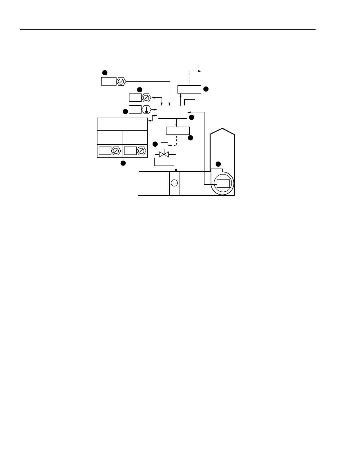
Item
No. Function
1 Control system energizes when fan is turned
on (See FAN SYSTEM START-STOP
CONTROL).
2 Space temperature inputs to control program.
3 Setpoint determines refrigerant on mode.
4 Refrigerant solenoid valve closes when fan is off.
5 Relay controls liquid line solenoid valve.
6 Relay enables compressor start control system.
7 Temperature differential determines
compressor off mode.
8 Compressor minimum on and minimum off
times prevent short cycling.
9 Control program coordinates cooling, safety,
and fan interlock control.
FEATURES
1. The refrigerant liquid line solenoid valve is closed and the
compressor cannot be energized when the supply fan is off.
2. Software time delays for compressor protection.
CONDITIONS FOR SUCCESSFUL OPERATION
The differential timers are set wide enough and the software
timers are set high enough to prevent short cycling of the
compressor under light load.
LIMITATIONS
1. Direct expansion coils are difficult to control from leaving
air due to the large and rapid temperature drop when
energized.
2. Compressor operating and safety controls must be
incorporated into the control system.
SPECIFICATIONS
See FAN SYSTEM START-STOP CONTROL.
The DX control system shall be enabled anytime the fan
operates.
Cooling system shall be cycled by a temperature control loop
with a 1.4 kelvins (adjustable) differential to maintain the space
temperature setpoint. When the system is commanded on by
the control program, it shall remain on at least eight minutes,
and when it is commanded off (or drops off during power
interruptions) it shall remain off at least ten minutes.
On a rise in space temperature to the setpoint, the refrigerant
liquid line valve shall open and a relay shall enable the
compressor to start under it’s controls.
When the space temperature drops to a value equal to the
space temperature setpoint minus a differential, the liquid line
solenoid valve shall close, and the compressor shall continue
to operate until shut down by it’s low-pressure cutout.
Refrigerant system control and interlock wiring shall be as
recommended by the compressor manufacturer.
TWO-POSITION CONTROL OF DIRECT EXPANSION COIL SYSTEM
Functional Description
M15170
4
MA
SA
ON
1
8
8
10
MINIMUM
ON TIME
MINIMUM
OFF TIME
COMPRESSOR
(MINUTES)
6
9
5
RELAY
RELAY
OPEN
CONTROL
PROGRAM
3
7
2
24.5
1.4
24.5
SUPPLY
FAN
TEMPERATURE
CONTROL
DIFFERENTIAL
(KELVINS)
TO
COMPRESSOR
START
CIRCUIT
COMPRESSOR
VOLTAGE MONITOR
 Loading...


