ENGINEERING MANUAL OF AUTOMATIC CONTROL
CHILLER, BOILER, AND DISTRIBUTION SYSTEM CONTROL APPLICATIONS
343
Table 4. Variable Speed Pump relationships
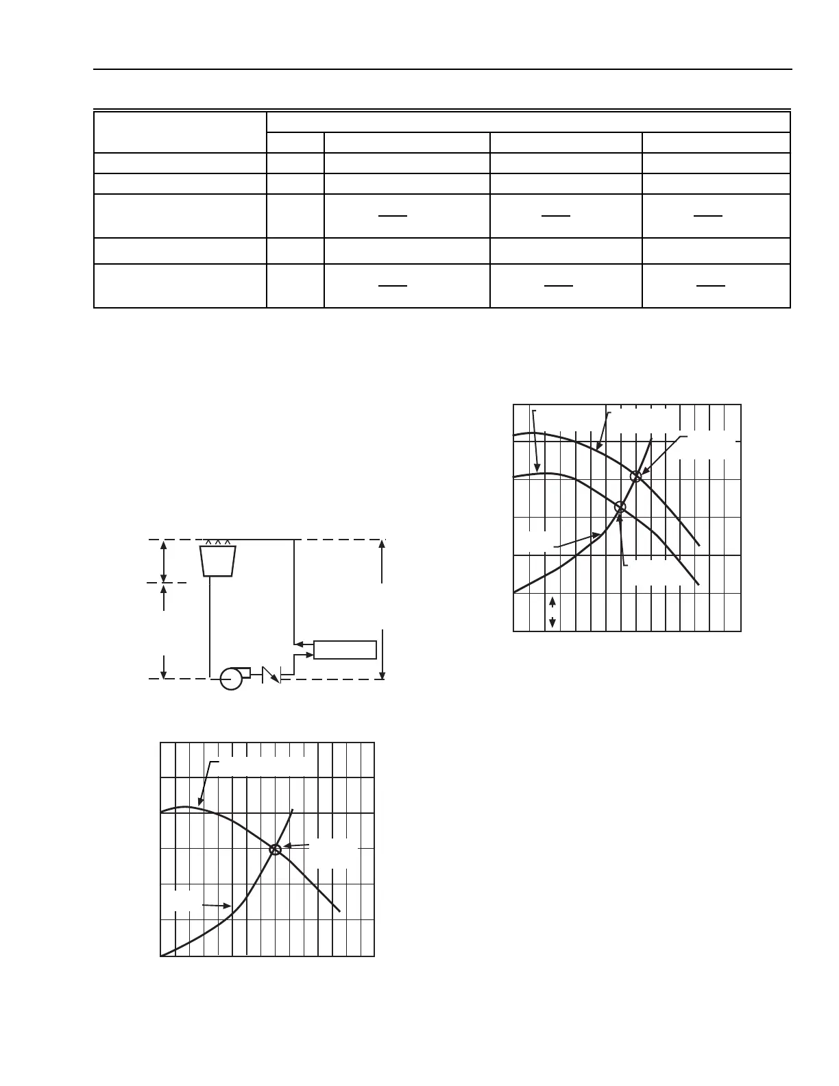
Figure 64 shows the system curve adjusted for the 30 kPa of
static pressure and the actual operating points of Pump A
(selected in Figure 63) and Pump B. Notice Pump A supplies
only 10.5 L/s at 125 kPa.
PUMPS APPLIED TO OPEN SYSTEMS
In cooling towers (Fig. 62) and other open systems, static
pressure must be considered when establishing system curves
and selecting a pump. Notice that the 27m of vertical pipe
(270 kPa static discharge pressure) is partially offset by the
24m of vertical pipe (240 kPa static suction pressure) in the
suction line. When a system curve is drawn for such a system,
static pressure of the tower must be added to the system curve.
The system is designed to operate at 12 L/s against 90 kPa for
piping and valves. The system curve in Figure 63 is drawn
through zero pressure (ignoring the 3m or 30 kPa static
pressure) which leads to choosing Pump A.
Fig. 62. Typical Cooling Tower Application.
Fig. 63. System Curve for Open
Circuit without Static Pressure.
Fig. 64. System Curve for Open
Circuit with Static Pressure.
MULTIPLE PUMPS
Multiple pumps are used when light load conditions could
overload a single pump. These conditions normally occur when
two-way control valves are used in the control system. Two-
way control valves sharply reduce flow when they begin to
close. Figure 65 shows that in a single-pump system, over
pressure can result at low flow. At one-third flow, the pump
pressure has increased, the source and piping drop is reduced
to one-ninth of the design drop, and the control valve drop has
increased greatly. Bypass, variable speed, or throttling valve
pressure relief should be used with a single pump. Where the
heat exchanger (such as a chiller) requires a high minimum
flow rate, a single pump is used, and diversity is not used, three-
way load control valves should generally be used.
CONDENSER
12 L/s
COOLING
TOWER
27m
STATIC
DISCHARGE
PRESSURE
(270 kPa)
3m
TOTAL
STATIC
PRESSURE
(30 kPa)
24m
STATIC
SUCTION
PRESSURE
(240 kPa)
C4096
FLOW IN L/s
TOTAL PRESSURE (kPa)
180
150
120
90
60
30
0
3
6
9
12
15
18
21
C4097
PUMP A
PERFORMANCE CURVE
SYSTEM
CURVE
INDICATED
OPERATING
POINT
180
150
120
90
60
30
0
3
6
9
12
15
18
21
FLOW IN L/s
TOTAL PRESSURE (kPa)
30
C4098
ACTUAL
OPERATING
POINT PUMP B
PUMP B
PERFORMANCE
CURVE
PUMP A
PERFORMANCE
CURVE
SYSTEM
CURVE
ACTUAL
OPERATING
POINT PUMP A
Load (percent)
Condition 100 80 60 40
Flow (L/s) 31.5 0.80 x 31.5 = 25.2 0.60 x 31.5 = 18.9 0.40 x 31.5 = 12.6
Speed (rpm) 1750 0.80 x 1750 = 1400 0.60 x 1750 = 1050 0.40 x 1750 = 700
Total Pressure (kPa) 210
210 x
()
1400
1750
2
= 134.4 210 x
()
1050
1750
2
= 75.6 210 x
()
700
1750
2
= 33.6
Fully Open Valve Drop (kPa) 30
30 x 0.80
2
= 19.4 30 x 0.60
2
= 10.8 30 x 0.40
2
= 4.8
Motor Power (kW) 10.1
10.1 x
()
1400
1750
3
= 5.17 10.1 x
()
1400
1750
3
= 2.18 10.1 x
()
1400
1750
3
= 0.65
 Loading...


