perating and Installation
board are used to indicate call progress and call status. They a
also used to display error codes.
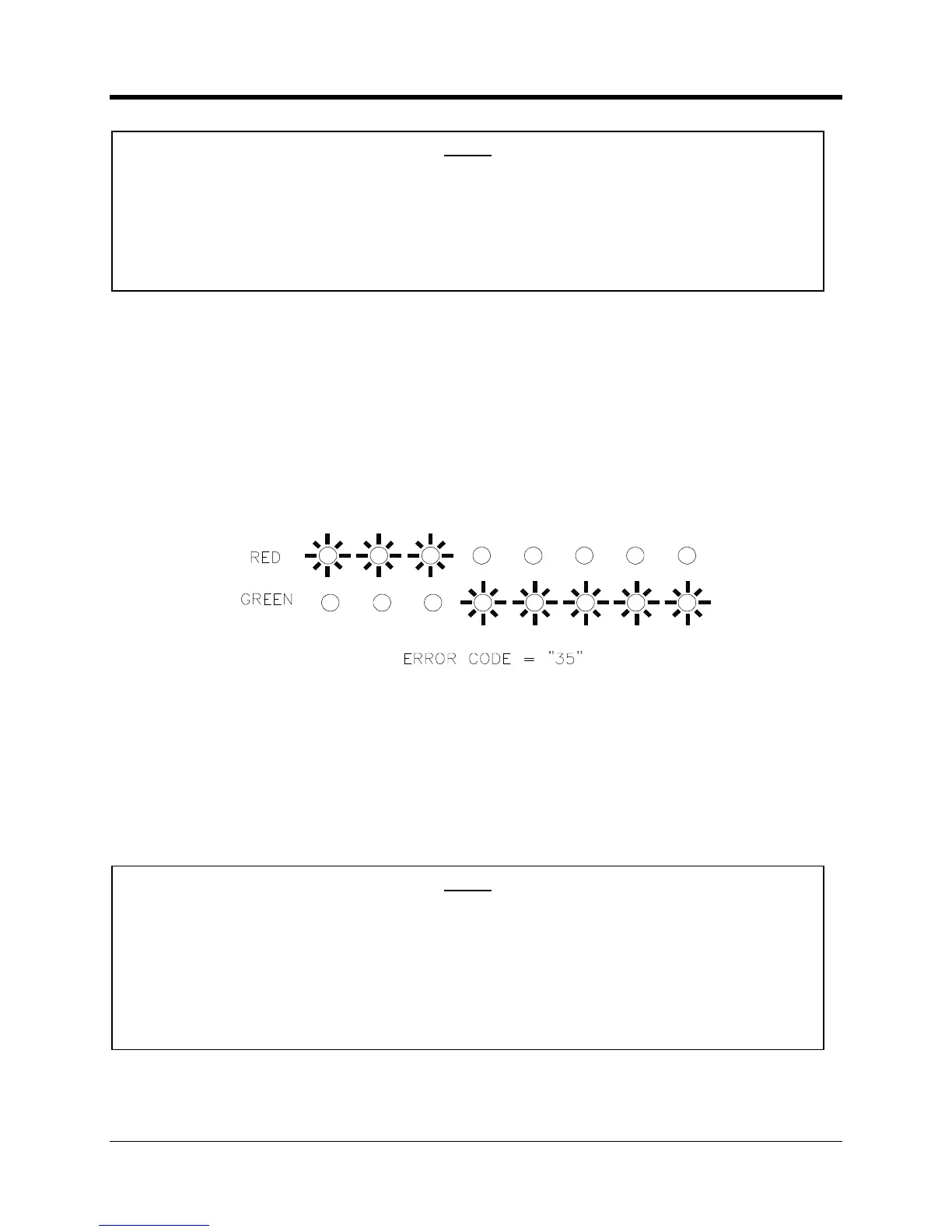
In the event of an error the LEDs will be flashed in a pattern that represents a 2
LED represents the first digit while the
LED the second digit. For instance, for
LED will flash 3 times and then the
An error code is displayed several times to allow the user to observe the pattern.
Example of Error Code “35” Display
Error codes are listed on the
The last 30 error codes are saved in the
’s memory and are reported to the data collection
system with each call, but only if calling into
15 minutes after the unit is powered
up or reset the LEDs will no longer display the call
progress. This is done to conserve power.
if a new call is triggered by the magnetic CALL switch or the TAMPER switch the
LEDs will be reactivated for another 15 minutes.
up or reset the LEDs will no longer display error
codes. This is done to conserve power. Errors that do occur will still be logged in memory
and reported to the data collection system.
However if a new call is triggered by the m
agnetic CALL switch or the TAMPER switch
then new error codes will be displayed for another 15 minutes.

 Loading...