perating and Installation
t is necessary to minimize power
r possible. The multiplexer board is based upon opto
consume power when enabled. For this reason the m
ultiplexer board is not powered
when in the process of active data exchange. This presents a problem in that the CNI2 will not
able to detect serial communications activity when the multiplexer board is powered down.
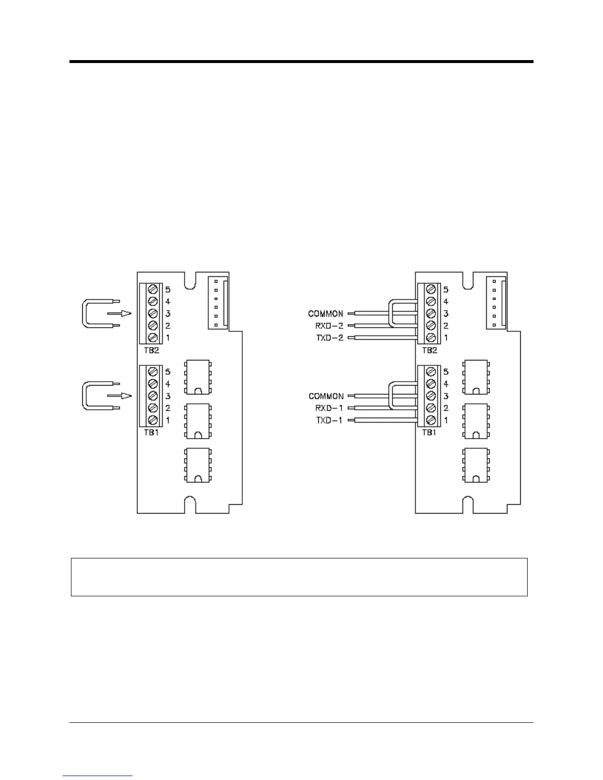
A simple method to resolve this is to wire the RXD signal coming from the external instrument in
parallel with both the RXD line and DTR input line. The multiplexe
r board is able to detect serial
data flow on the DTR line, even when in low power mode. This then enables the CNI2 board to
wake from low power mode, drive the multiplexer board, and subsequently receive serial stream
The illustration below shows
where the jumper wire is to be installed across the terminal block
ddition of a jumper wire as seen above is only required on the multiplexer board itself.
uld not be installed directly on the terminal block of the CNI2 board.

 Loading...