perating and Installation
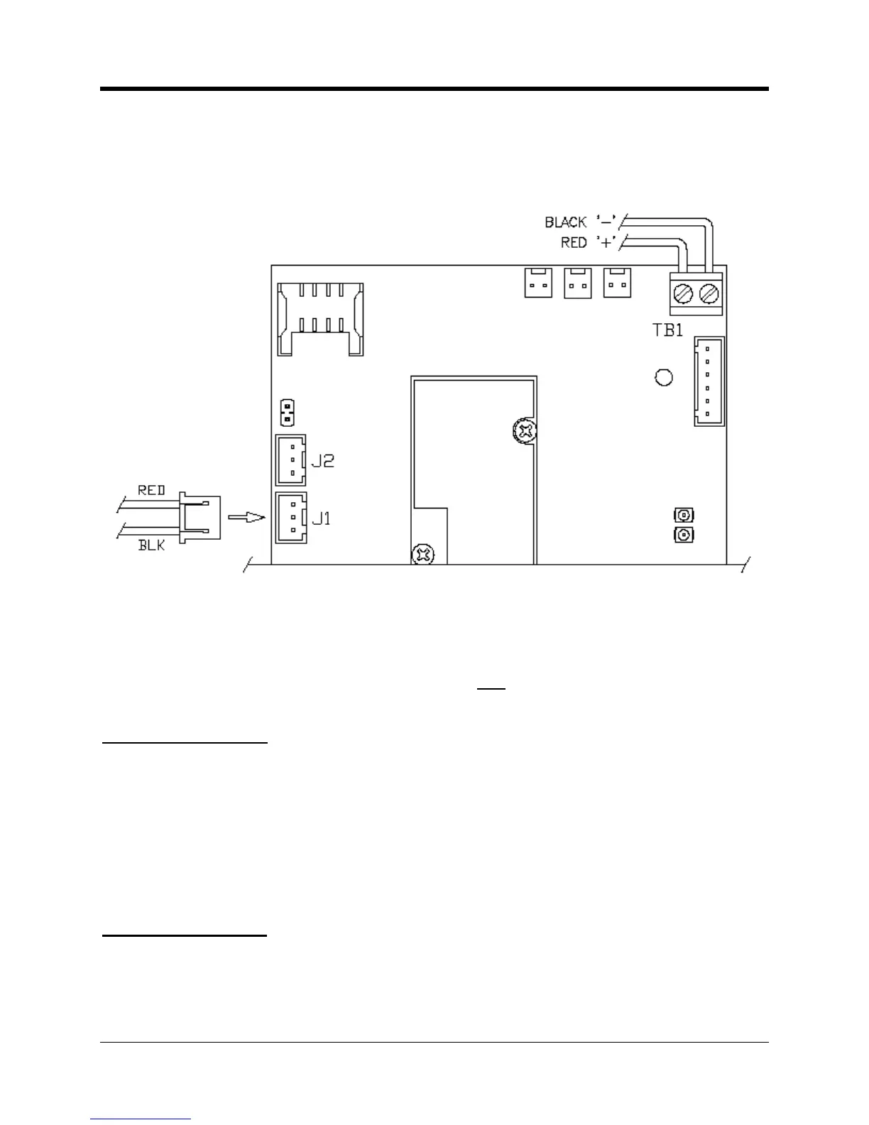
Illustrated below is a port
ion of the CNI2 board. TB1 is prewired at the factory to a high density
capacitor element to support peak load demands when operating the cellular radio. J1 and J2
are the power connectors for the CNI2. Additional details follow.
Connectors J1 & J2 are electrically equivalent, and it does not matter which of the two is used
for attachment to the power source. For a battery powered application it is recommended that
the fresh pack be plugged into an available connector
before disconnecting the depleted
The CNI2 has been designed to provide long service life when operating from batteries. Total
battery life is influenced by two factors in the CNI2; continuous background current and high
ent draw during cellular calls. The background current can be minimized to a certain extent
by using fewer pulse input connections and using normally
and alarm sensing. High current draw depends on the number and duration
made. This can be minimized by ensuring the CNI2 has strong cellular reception (which
minimizes call retries) and by limiting the number of regular scheduled calls to the extent
battery condition is triggered can be changed using the MP32
Normally the programming template provided by Mercury will have a
default value optimized for the application.

 Loading...