EasyManuals Logo
Home>Honeywell>Recording Equipment>CNI2

Honeywell CNI2 User Manual

Honeywell CNI2
162 pages
To Next Page IconTo Next Page
To Previous Page IconTo Previous Page
Page #155 background imageLoading...
Page #155 background image
CNI2
O
perating and Installation
Guide
154
Boost Capacitor
Connects to the TB1 terminal block and assists the battery pack during peak current events,
usually during radio transmission.
Low
-
Voltage Detector
Measured at the TB1, J1 and J2 power connectors, which ever has the highest voltage. A user
-
selectable alarm point in the range of 0.1
28 Vdc can be used to report low
-
voltage situations.
Power Input #3 (TB1)
Connector Type
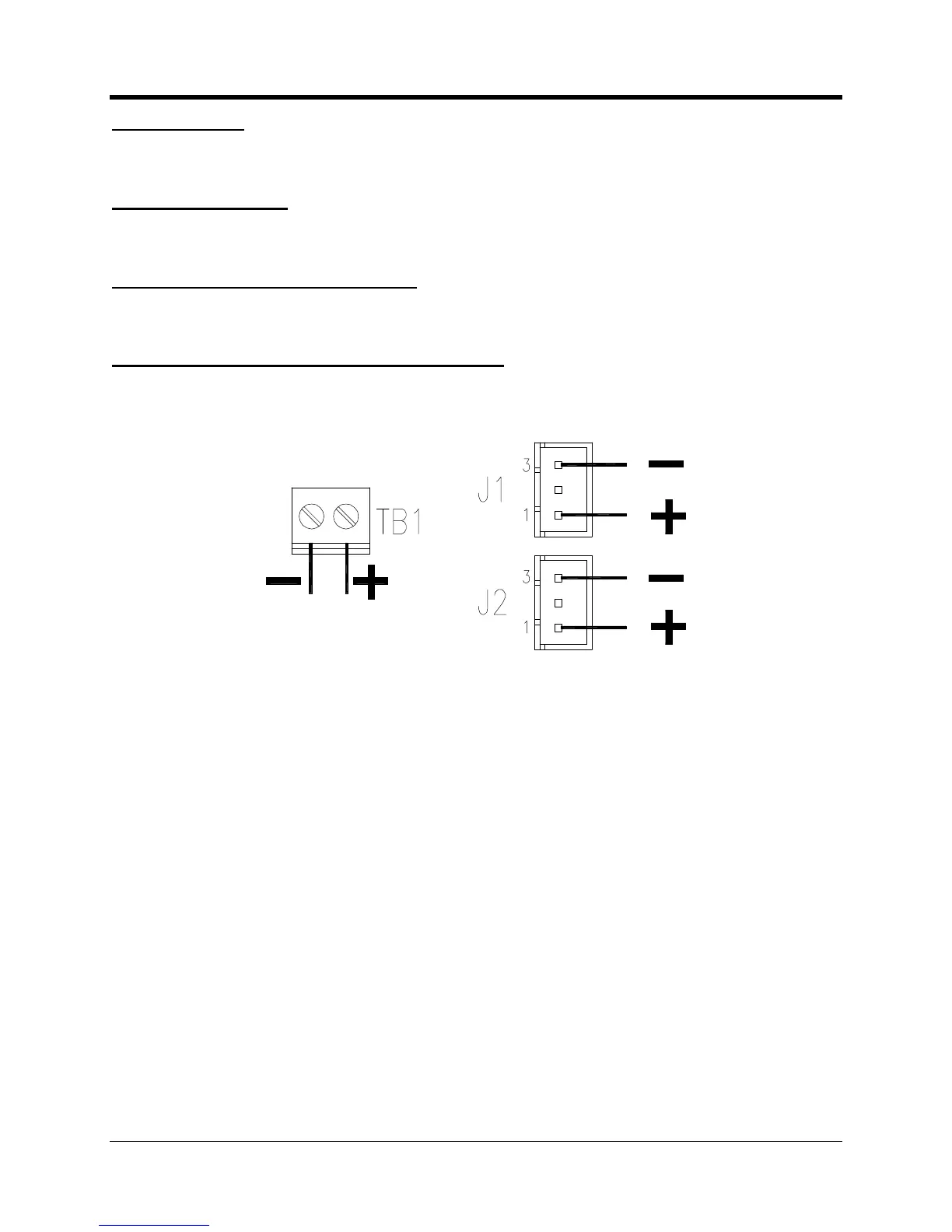
Screw terminal, 5.08 mm (0.2
”) spacing. 90º entry. 14
-
26 AWG (0.14
1.5 mm) wire size.
Maximum torque is 0.6
Nm (5.3 lbs.
-
in). See
next illustration
for polarity.
Power Input #1 & #2
(J1 and J2)
Connector Type
3
-
pin JST B3B
-
XH
-
A. Recommended mating connector is
JST XHP
-
3 connec
tor housing with
two SXH
-
001T
-
P0.6 female contacts. See
next illustration
for polarity.
Power Input Connector Polarities

Table of Contents

Questions and Answers:

Question and Answer IconNeed help?

Do you have a question about the Honeywell CNI2 and is the answer not in the manual?

Honeywell CNI2 Specifications

General IconGeneral
BrandHoneywell
ModelCNI2
CategoryRecording Equipment
LanguageEnglish

Related product manuals