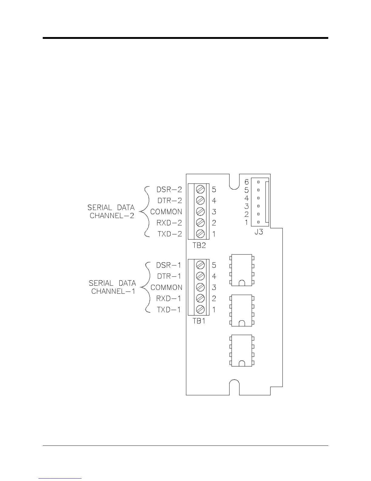
perating and Installation
below. The connector J3 is pre
not included with the assembly
r connection to external devices. An example might be two ECAT electronic
correctors at a field site.
the configuration has both the multiplexer board and the RS
485 as part of the system, then
only terminal block TB2 is available for wiring to an ext
232 device. TB1 will have been
485 board, which has its’ own connector for external wiring to an RS
Please note that the TXD line is a driven output, RXD is an input, DSR is a driven output, and
R is used as a wakeup trigger. The following page describes the DTR function and wiring
connection in more detail.

 Loading...